Let's Design and Build a (mostly) Digital Theremin!

Posted: 8/15/2023 6:56:15 PM
dewster

From: Northern NJ, USA

Joined: 2/17/2012

Mad Scientist Time!

Ordered a function generator for coil testing and it arrived today.  Two channels let you do rotating Lissajous figures like you see on the CRT screens of 50's Sci-Fi B movies:

It's a UNI-T UTG932E: https://www.amazon.com/dp/B0BP64GHDK?th=1.  I watched a bunch of videos and read a bunch of reviews before purchasing it.  The lower end DDS based units seem rather crude, though I would have gone for one were they a bit less expensive for what you get.  In the end the choice came down to the UNI-T vs. OWON DGE2070 (https://www.amazon.com/dp/B0BPY2MJDF).  The OWON looks better on paper, but every UI change seriously glitches the output, and in the respective teardowns the UNI-T has a cleaner PCB layout.

The unit is quite cute, it looks like a tiny oscilloscope.  You can set it upright or lay it flat on its back if you like.  A screensaver kicks in at some point to prevent LCD burn-in.  Backlit rubber buttons seem OK, encoder implementation is fine, UI isn't too tricky.  Still don't know how to pronounce "Lissajous" though.

Posted: 8/15/2023 8:12:15 PM
André

From: 30 km south of Paris (France)

Joined: 12/23/2022

Still don't know how to pronounce "Lissajous" though.

Jules Antoine Lissajous (1822-1880), mathématicien français.

How to pronounce his name.

Posted: 8/15/2023 8:22:50 PM
dewster

From: Northern NJ, USA

Joined: 2/17/2012

"How to pronounce his name."  - André

Thanks!

Posted: 8/17/2023 11:54:58 AM
dewster

From: Northern NJ, USA

Joined: 2/17/2012

Sallen-Key Q & Z

Looking at the circuit again:

I think it's clear where the Q comes from and why it's so sensitive to gain=1.  The voltage at Cant is tracked ~1:1 by op-amp E1, with positive feedback through C1 and R2.  So both ends of R2 are at essentially the same voltage and the current through it is minimal, which makes R2 effectively a much higher impedance.  Sort of an inverse Miller capacitance type situation.  Making C1 smaller or E1 gain slightly smaller increases the voltage difference across R2, leading directly to increased damping (i.e. decreased Q).

For temperature dependence / drift, C1 should probably be NP0 / C0G, which might limit the Q to 100 or so max, which probably isn't a big deal.  I wonder what kind of VCC headroom might be necessary to accommodate mains hum picked up by Cant?

It's interesting that the current into R1 is rather typical of real inductor drive (+/- 1.5mA for 1V signal in).

Posted: 8/25/2023 4:49:15 AM
André

From: 30 km south of Paris (France)

Joined: 12/23/2022

Looks like Anca Bold Martin plays a D-Lev.

Posted: 8/25/2023 6:12:32 PM
dewster

From: Northern NJ, USA

Joined: 2/17/2012

"Looks like Anca Bold Martin plays a D-Lev."  - André

Yes, and playing it quite well indeed!  Anca and her husband designed the case.

Posted: 8/28/2023 10:22:32 AM
dewster

From: Northern NJ, USA

Joined: 2/17/2012

Choking Up

Evan had RF chokes custom wound and very generously sent some of them to me - along with one of his D-Lev builds!   Thanks Evan! 

Anyway, I finally got around to examining Evan's coils.  Tested were my 1mH and 2mH single layer solenoid kit coils, a 50mH Bourns ferrite RF choke that was lying around, and Evan's 1, 2, 10, and 20mH non-ferrite chokes.  The D-Lev LC-DPLL range was too limited to perform some of the tests, as was the upper ~2MHz limit of my function generator, so full testing had to wait until my function generator arrived last week.


Above: Evan's chokes on the left, Bourns 50mH on the right; kit coils not shown.


Above: Notebook scan of test results.

The scope probe C is fairly close to Theremin antenna C, so I tried to use just this as the test load.  But the 10meg R to ground is a Q killer, so the probe Z had to be somewhat isolated by a roughly 1:12 C divider.  This divider is exposed to strong field voltages so it isn't super accurate, but at least it gives a more or less apples to apples type comparison with a fairly realistic C load.

What jumps out at me here is the low Q of the 1mH and 2mH chokes.  The SRF Q is even lower for all of the chokes, but is higher for the kit coils.  I thought high Q would correlate with high SRF, but all of the chokes & coils are quite similar here (the SRF/Jig ratio).

The 10mH and 20mH chokes fared better than the 1mH and 2mH chokes in the Q department, and moved the operating point below the AM band, which is also desirable.  During the testing it was quite evident that the kit coils were drawing much more current than the chokes at resonance, as I had to adjust the generator amplitude to compensate (50 ohm output).  This is another indication of high Q and high SRF.  The resonance of the kit coils corresponded with a very close phase quadrature between drive and sense, whereas the chokes displayed some phase offset - this is an indication of not insignificant parasitic C, and not surprising given the small physical form of the other chokes.

So I don't know exactly what to make of all this.  I'd like to get out from under all the winding.  I'd like higher inductance values to lower the operating points, but that means even more winding / finer wire / larger forms.  Physically larger coils have lower parasitic C.  Users wouldn't exactly be surprised / upset to see big honkering coils on their Theremins, particularly if they are pretty, thought that could impact portability.  Someone had a choke type plastic bobbin, with walls supporting the donuts rather than a fancy winding and varnish.  The slots could then be simply filled one at a time scramble wound.  Something like that could be easily 3D printed.  I've read that even the varnish hurts the Q, and that the ideal wire spacing is usually larger than the varnish can provide.

Posted: 8/29/2023 7:49:58 PM
dewster

From: Northern NJ, USA

Joined: 2/17/2012

Drop To A Knee

I've been working on the volume field Drop knob for the past week or so.  The old and new both introduce a second order curve towards silence, but the old one started out with a slope of 1:1 from zero, which only increased with the knob setting.  The new one pivots about -12dB, so it compresses the 0 to -6dB region at higher knob settings, which I think is what many analog players may be seeking in terms of a volume field response:

As you can see from the above manual excerpt (the knee knob functionality hasn't changed, it is only included here for comparison purposes) Drop[5] now gives an expansion of -12dB over the 0 to -36dB range of hand movement, so what would normally be the bottom LED fully lit on the tuner volume thermometer graph becomes all LEDs off (-36dB => -48dB).  This is a moderate expansion and almost too subtle to feel, but can provide a bit of added silence if needed.  Drop[16] is around where I prefer to set it, a slight compression of the top LED and 12dB of expansion over the -12dB to -24dB hand movement region.  Drop[31] is likely what most analog Thereminists are looking for, a strong 3:1 compression of the top 6dB, and a 3:1 expansion of -12 to -24dB, which gives a more theatrical expressive region if one uses traditional volume sense (farther=louder).

Before this exercise I thought that any desired non-linearity could be obtained via the field null location knob Vcal.  Two huge problems with this approach are:

1. It takes a ton of null adjustment to strongly influence the mid to near field linearity (which is where the volume field normally functions).
2. Working with a fundamentally non-linear field means all field adjustments go out of whack when you simply move the field via the Ofs- / Ofs+ knobs (one way to look at this is the adding of logarithms is actually a multiplication).

So, even if your final goal is a non-linear field, there are very strong reasons to start with a linearized field and build from there.

Drop is implemented by cross-mixing the linear and 2nd order responses in the code.  I almost always implement knobs with [0] off, mid values the most musically useful, and max values in crazy town.  In this instance I think going from a linear knee with Drop[0] to second order knee with Drop[31] seems warranted, even though Drop[31] isn't exactly berserk territory.  I also feel that the old Drop functionality was a bit too wild at maximum, and an invitation to disaster.

And, having spent a certain amount of time and effort linearizing the fields, it's taken me like forever to come to the realization that some non-linearization  may actually be advantageous.

Posted: 9/18/2023 2:06:55 PM
dewster

From: Northern NJ, USA

Joined: 2/17/2012

Velocity Preciosity

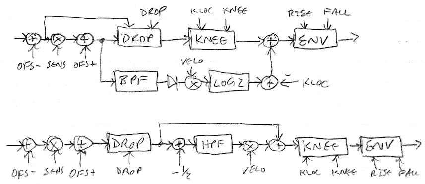
For the last couple of weeks I've been revisiting the volume hand velocity sensing for what seems like the 100x time.  I've finally been able to resolve several long-standing issues and misunderstandings on my part.  Meet the new velocity (bottom) - somewhat different than the old velocity (top) - and now an entirely rational construct with no hand-waving necessary to explain how it works:

First off, a bit of history.  Long ago I tried differentiation to detect velocity from position.  This makes sense from a calculus standpoint, but it of course unacceptably gains up high frequency noise because differentiator gain is infinite at infinite frequency.  I thought to follow it by a second order low-pass filter set high enough, but then hit on using a 10Hz 2nd order band-pass filter, which is essentially a 1st order high-pass followed by 1st order low-pass.  This worked well and certainly tamed any high frequency noise, but wasn't entirely linear with velocity, was rather complex, and suffered from integrator wind-up.  This was followed by a LOG2 function which only accepts unsigned input, so the velocity feeding it had to be rectified.  The output was offset by the kloc value to gain up the far field, with this velocity detector placed in parallel with the volume knee.  I see now that all of these decisions were sub-optimal (that's engineer-ese for "mistakes were made").

After the failures of the differentiator trials, the next logical step would have been to try a simple 1st order high-pass filter.  It would be linear in velocity if operating below the cutoff, and setting the cutoff to something reasonable would limit low frequency gain down (and thus limit high frequency gain up by minimizing the post multiplication strength) and minimize the accumulator wind-down time, but I suppose I was too spooked by the previous differentiation noise to even consider it.  Anyway, this is the more correct solution over 2nd order band-pass.

The more I looked at the LOG2 function the more I realized that it's basically just an enormous gain-up.  It takes an integer input and necessarily outputs a 5.27 fixed point number, so any input greater than 1 will give at least 1 << 27 as an output, and I don't believe the LOG2 curve itself comes meaningfully into play.  I remember initially trying square root (which yields a similarly large 16.16 result) but LOG2 worked better, and it was going down this false path that probably led me more astray than anything else - I couldn't really explain or entirely justify it to myself, and at some point just stopped thinking about it.  Pure gain (multiplication) actually works just fine and it accommodates signed I/O as well to give bi-directional velocity.

Any filter output multiplied up and combined with the input and then limited will suffer from accumulator wind-up, where the filter continues to function while the output is otherwise pegged.  I played with a spreadsheet sim for several days trying to eliminate it, and discovered that setting the cutoff frequency higher during output saturation went a long way towards minimizing it, but it audibly glitched when limiting so I had to remove it.  I believe the right way to do all this is to use division to work backwards from the gain-up, but I don't have sufficient cycles remaining on the volume field thread.

So the velocity unit now uses a 40Hz first order high pass filter to detect velocity, and the velocity is now applied bidirectionally rather than just for the attack, so it can also be used to more quickly drive the volume to zero. The day before yesterday I thought to position the velocity unit before the knee unit rather than in parallel with it, and after playing it for a while think it's a keeper.  The following knee gains up attack and decay, and this - along with the higher cutoff frequency and bidirectional velocity - tend to hide the filter wind-up, so higher velocity settings don't cause large attacks to rail at max volume for a noticeable period, followed by a weird decay (having an RC exponential decay go through the EXP2 function at the end gives who knows what).  Limiting the high-pass filter input to [-98:0] dB gives a nice range in the field (you don't want significant subsonic operation) and also prevents saturation of the filter output.

I considered having the velocity unit be the only input the envelope generator, but the knee provides the lion's share of attack sharpness, so it must somehow also be an input to the envelope generator, and can't bypass it.

So we can use the velocity to drive the volume level up through the knee and back down again, which seems like a good thing in practice.  Having the drop before all this adds even more to low volume velocity gain, which I thought might be problematic but it doesn't seem to be.  I think it's best to have all of these units in series if at all possible, as the simpler processing may feel more intuitive to control with the hand.

[EDIT] You can listen to the new velocity (followed by a fairly sharp knee) in the trumpet_Bb preset here: https://d-lev.com/audio/2023-09-17_velocity.mp3

Posted: 9/18/2023 10:37:49 PM
Mr_Dham

From: Occitanie

Joined: 3/4/2012

Where is MIDI vloc threshold detection on the drawing before and after the change ?


You must be logged in to post a reply. Please log in or register for a new account.