Teensy 4.0 600MHz ARM Cortex M-7 MCU - ideal for digital MCU based theremin?

Posted: 2/27/2020 8:57:45 PM
dewster

From: Northern NJ, USA

Joined: 2/17/2012

"BTW, how do you estimate latency introduced by IIR filter, it has infinite response?
Passing step signal on it, checking how fast it changes? What is threshold?
Can we count time to reach 1/2 of target value, 2/3, or something like this?"  - Buggins

Well, RC time constant is exactly:

RC = 1/(2*pi*f)

This gives rise time from 36.8% threshold to 63.2% threshold for a step input.
Multiply this by 1.4 for 20% / 80%
Multiply this by 2.2 for 10% / 90%

For f = 100Hz we get 1.6ms, or 2.2ms, or 3.5ms.  But of course RC has not very much slope to the cutoff skirt, so lots of HF content gets through, which helps to "sharpen up" the output.  Higher order filters will necessarily have slower rise times, with some forms slower (Butterworth, Elliptic, etc.).

The good thing about IIR filter inertial delay is that, with a change at the input, the output starts changing immediately.  And since a lot of Theremin movement isn't instantaneous, the slowness usually isn't obvious because a somewhat slow filter can track slow actions pretty well.

Whereas with transport delay the output is almost always somewhat wrong.

In conclusion, once you have your bandwidth set high enough to track whatever is going on at the input (or high enough to exceed human perception limits) then the filter won't be noticed.  It's not super scientific, but for a pro instrument I'd recommend 100Hz inertial as a design target and maybe < 5ms transport as a design limit.  For something really inexpensive these might be 10Hz inertial, maybe <  30ms transport.  Go too low on the inertial and, as you say, vibrato starts getting murdered.

Posted: 3/5/2020 7:40:25 PM
dewster

From: Northern NJ, USA

Joined: 2/17/2012

Vadim, I believe that my "oscilloscope axis processing" approach [link] is extremely similar to the approach you've investigated here lately, though mine is a first order integrate-and-dump process, and yours is a more continuous second order process.  Mine uses the measurement period to kill hum, and I'm wondering if yours could be adapted to do the same?  Could you somehow arrange things so that the "ends" of the difference are 1/60Hz or 1/50Hz apart?  Or close to this?  The first order process really kills hum (you can clearly see this on the scope by setting the horizontal delay to something substantially different than the inverse of the mains frequency) but allows RF to alias.  Your second order process could kill hum and some RF too.

Posted: 3/6/2020 1:16:14 PM
Buggins

From: Porto, Portugal

Joined: 3/16/2017

Vadim, I believe that my "oscilloscope axis processing" approach [link] is extremely similar to the approach you've investigated here lately, though mine is a first order integrate-and-dump process, and yours is a more continuous second order process.  Mine uses the measurement period to kill hum, and I'm wondering if yours could be adapted to do the same?  Could you somehow arrange things so that the "ends" of the difference are 1/60Hz or 1/50Hz apart?  Or close to this?  The first order process really kills hum (you can clearly see this on the scope by setting the horizontal delay to something substantially different than the inverse of the mains frequency) but allows RF to alias.  Your second order process could kill hum and some RF too.


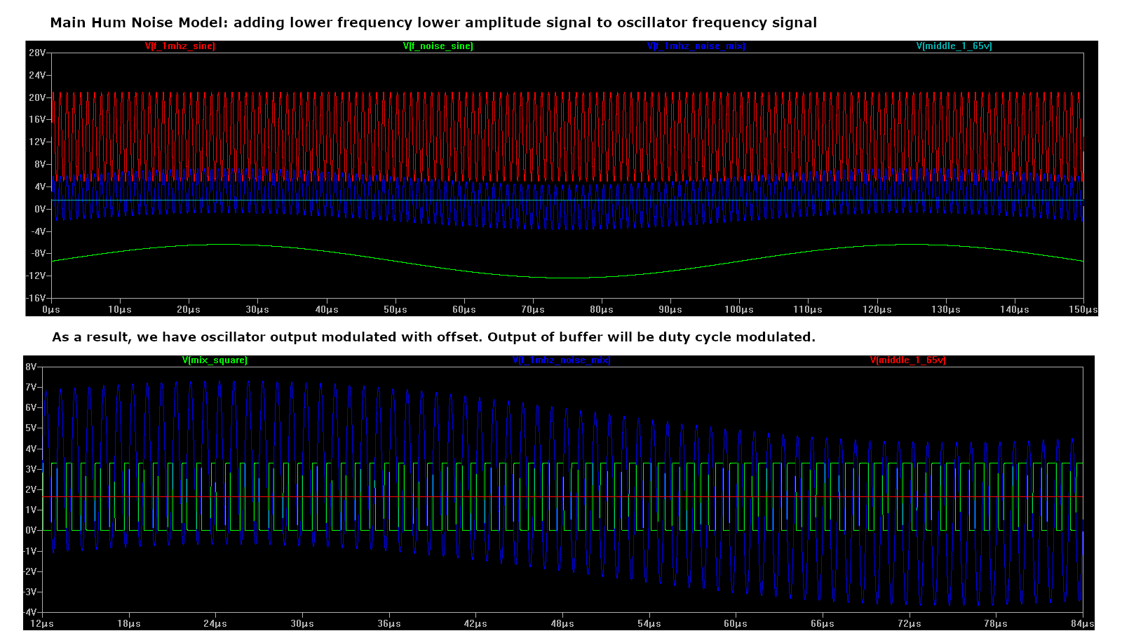
Main Hum Noise investigations.

Trying to understand how main hum noise is visible in oscillator square output.

Assuming that 50 or 60 Hz periodic, almost sine, signal is added to oscillator signal.

It has 15000..20000 lower frequency and much lower amplitude than main oscillator signal.

I believe it works like slowly changing "DC Offset" for oscillator output, resulting in PWM duty cycle modulation of oscillator output.

On simulation results below, higher amplitude and higher frequency noise signal is used to emphasize effect introduced by noise to oscilaltor square output.

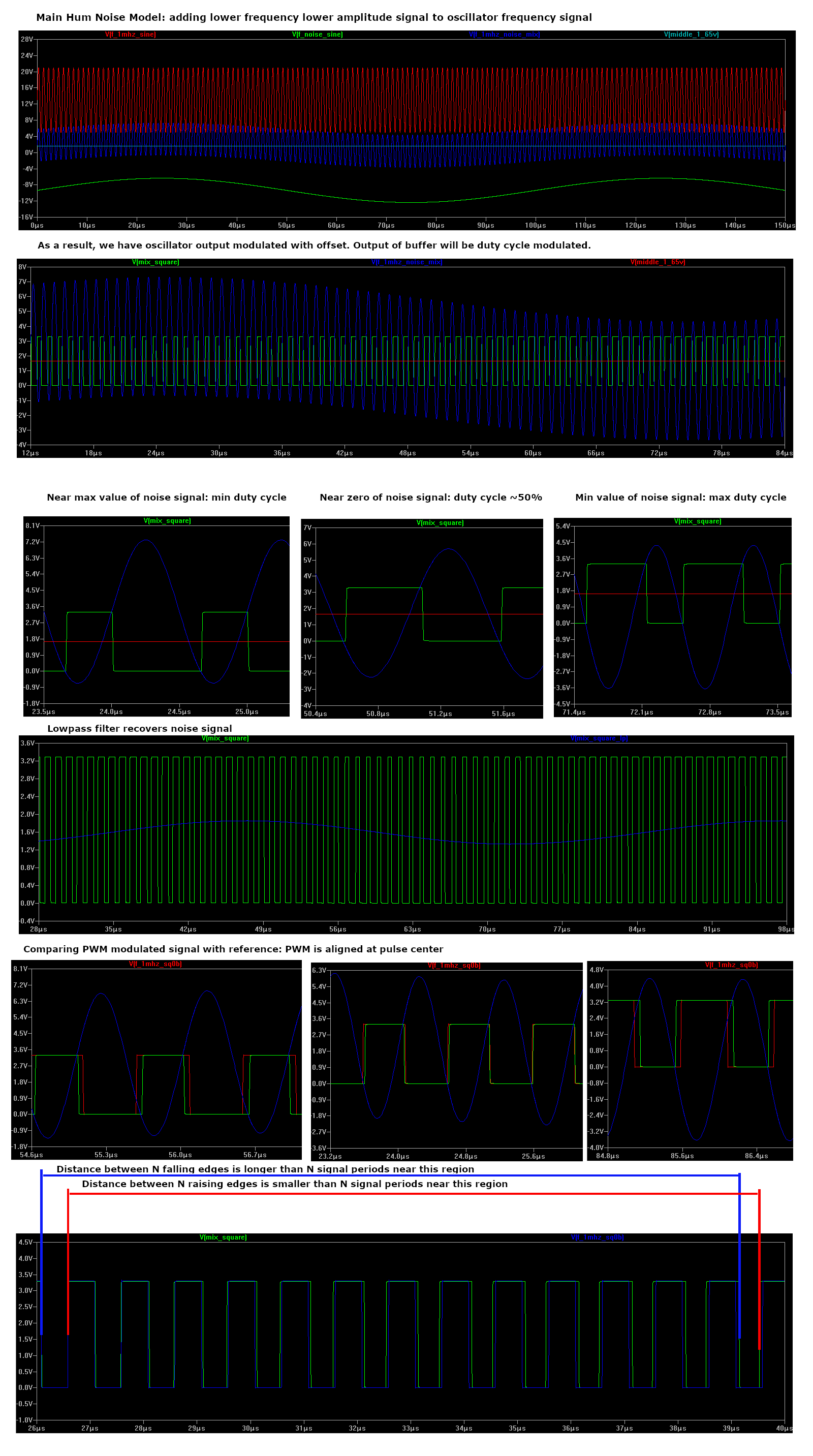
On last image we can see that if we try to calculate oscillator signal period based on raising or falling edges, we will have different values at different points, depending on local main hum noise offset.

At points near noise crossing zero, difference is almost 0. But near noise peaks, we can see maximum error values introduced by noise.

Error value (difference between measured signal period and real exact value) will be 50 or 60Hz sine with some amplitude. For far hand distance this offset will produce audible modulation of calculated hand to antenna distance.

How can we suppress it? Bandstop filter at noise frequency? No! There is a simple solution.

Oscillator output signal has duty cycle modulated by lower frequency (main hum). But fortunately, pulses are actually (almost) synchronous to pulse center points.

If we take pulse centers (average between raising and falling edge, or falling and raising) we will get positions of oscillator signal peaks instead of zero crossing.

Peak positions are not affected by DC offset, and can be used for calculation of oscillator signal period with noise removed.

The only concern: near noise peak, middle point between raising and falling edge is accurately centered at oscillator signal peak. But between peaks (with max effect near noise zero crossing),
"DC offset" from horizontal line is transformed to raising and falling, giving offset of middle edge position from real peak value. But I hope this effect is eliminated by high F_osc/F_noise rate.
"DC offset" inclination is stretched 15000 times, producing "almost const" at oscillator period scale. As well, it's reduced by high V_antenna / V_noise rate.


Initial plan of Teensy 4 sensor was:

Oscillator square output passed to 240MHz time capture input: timer will capture timer counter values at raising and falling edges of input signal and write them to circular buffer using DMA.
Captured values have low precision: for 1MHz oscillator frequency, timer counter changes ~240 times per one oscillator period.
Difference between edge position and position of previous edge of same type will be only ~280 == ~8 bits. But since signal period changes only by 5% for whole working hand to antenna distance, only 3.5 bits of 8 provide hand position information.
We can use averaging to collect more bits.
Taking position of both edges gives 1 more bit.
Stage 1 processing: subtract recent edge position from same edge position delayed by N oscillator cycles - gives log2(N) exact bits, introducing N/2 oscillator periods latency (averaging signal for N periods).
Stage 2: 4 stage IIR on stage 1 output to extract more useful bits from lower bits dithering of stage 1 output.
Simulation shows that for 99% of oscillator frequencies it's possible to collect >=28 bits of meaningful bits.
Although, the rest, near rational multiply points F_timer * A / B, there are artifacts which reduce number of bits to 20-22. Anyway, it should be enough for distances up to 60cm.


Let's modify averaging algorithm to filter out main hum noise.
Actually, it's already filtered out (it's a reason why I was unable to reproduce it on simulation).
From stage 1, samples are coming interleaved, corresponding to falling / raising edges. Average of two sequential values is actually exact oscillator frequency period. Stage 2 filter filters out odd/even samples jumping.

But just in case, we can modify stage 1.
Instead of returning (sample_buffer[pos] - sample_buffer[pos - N]), we can return (sample_buffer[pos] + sample_buffer[pos-1] - sample_buffer[pos - N] - sample_buffer[pos - N - 1]) which gives difference between peaks instead of edges.


FPGA implementation

While waiting for my small oscillator PCBs for Tube Monster design (they are leaving chinese customs now), I've reimplemented Xilinx FPGA based sensor with new design.

While designing, I'm trying to minimize resource usage still keeping high sensitivity.


Stage 0: oversampling_edge_detector module - provides sequence of timer counter values captured on each input pin edge. Low frequency timer counter is working at 150MHz. Worse than Teensy 4? No.
There are ISERDESE2 modules implementing 600MHz*DDR=1200MHz signal deserialized 8-bit values at 150MHz. Optionally 2 / 4 / 8 of such modules can work together to provide 16, 32, or 64 deserialized bits per 150MHz cycle.
IDELAYE2 modules are used to provide different input delay for each of ISERDESE2. Delays are distributed equally to cover 1200MHz period.
With x8 delay based oversampling, module measures edge position with 9.6GHz cycle precision.
Lower 3..6 bits of module output are gained using oversampling, higher bits are low frequency counter bits.

Code:
module oversampling_edge_detector
#(
    // oversampling bits, 0=no delay based oversampling, 1=combine 2 iserdes, 2=combine 4 iserdes, 3=combine 8 iserdes
    parameter OVERSAMPLING = 3,
    // reference frequency for delay line, in MHz
    parameter DELAY_REFCLOCK_FREQUENCY=200.0,
    // number of bits in timer cycle counter (8 bits for 150MHz->1MHz, 6 bits for max filter stage1 delay)
    parameter COUNTER_BITS = 8 + 6
)
(
    // ~600MHz
    input logic CLK_SHIFT,
    // ~600MHz, phase inverted CLK_SHIFT 
    input logic CLK_SHIFTB,
    // ~150MHz, must be phase aligned CLK_SHIFT/4 
    input logic CLK,
    // reset, active 1, must be synchronous to CLK_SHIFT !!!
    input logic RESET,
    // counter enable, active 1, keep inactive for 4 CLK_SHIFT cycles adter RESET deassertion
    // must be synchronous to CLK_SHIFT !!!
    input logic CE,
    // serial input
    input logic IN,
    // 1 for one cycle if state is changed
    output logic CHANGE_FLAG,
    // 1 if change is raising edge, 0 if falling edge
    output logic CHANGE_EDGE,
    // counter value for edge    
    output logic[3 + OVERSAMPLING + COUNTER_BITS - 1 : 0] EDGE_POSITION
);

Resource utilization for max oversampling (9.6GHz resolution, 14 bits output), recommended for Pitch axis:

+-----------------------------+------+-------+-----------+-------+
|        Site Type            | Used | Fixed | Available | Util% |
+-----------------------------+------+-------+-----------+-------+
| Slice LUTs*                 |   56 |     0 |     17600 |  0.32 |
|   LUT as Logic              |   56 |     0 |     17600 |  0.32 |
|   LUT as Memory             |    0 |     0 |      6000 |  0.00 |
| Slice Registers             |   86 |     0 |     35200 |  0.24 |
|   Register as Flip Flop     |   86 |     0 |     35200 |  0.24 |
|   Register as Latch         |    0 |     0 |     35200 |  0.00 |
| IDELAYE2/IDELAYE2_FINEDELAY |    8 |     0 |       100 |  8.00 |
|   IDELAYE2 only             |    8 |     0 |           |       |
| ILOGIC                      |    8 |     0 |       100 |  8.00 |
|   ISERDES                   |    8 |       |           |       |
+-----------------------------+------+-------+-----------+-------+


Resource utilization for min oversampling (1.2GHz resolution, 11 bits output), recommended for Volume axis:

+-----------------------------+------+-------+-----------+-------+
|        Site Type            | Used | Fixed | Available | Util% |
+-----------------------------+------+-------+-----------+-------+
| Slice LUTs*                 |   12 |     0 |     17600 |  0.07 |
|   LUT as Logic              |   12 |     0 |     17600 |  0.07 |
|   LUT as Memory             |    0 |     0 |      6000 |  0.00 |
| Slice Registers             |   20 |     0 |     35200 |  0.06 |
|   Register as Flip Flop     |   20 |     0 |     35200 |  0.06 |
|   Register as Latch         |    0 |     0 |     35200 |  0.00 |
| IDELAYE2/IDELAYE2_FINEDELAY |    0 |     0 |       100 |  0.00 |
| ILOGIC                      |    1 |     0 |       100 |  1.00 |
|   ISERDES                   |    1 |       |           |       |
+-----------------------------+------+-------+-----------+-------+


Stage 1: delay_diff_filter module - takes output of stage 0 (sequence of timer counter values, interleaved captured on raising / falling / ... edges).
On each new input value, we put it to circular delay buffer and calculate new output value.

OUT = BUF[pos] - BUF[pos - DELAY_CYCLES]

This stage gives additional exact log2(DELAY_CYCLES) useful bits of data, introducing (1/F_osc)*DELAY_CYCLES/4 latency.

Code:
module delay_diff_filter
#(
    // filter will calculate diff with value delayed by DELAY_CYCLES WR cycles, power of two is recommended
    parameter DELAY_CYCLES = 64,
    // number of bits in value (the bigger is delay, the more bits in value is needed: one addr bit == +1 value bit)
    parameter VALUE_BITS = 20,
    // use BRAM for delays with log2(DELAY_CYCLE) >= BRAM_ADDR_BITS_THRESHOLD
    parameter BRAM_ADDR_BITS_THRESHOLD = 7
)
(
    // clock signal, inputs and outputs are being changed on raising edge of this clock 
    input logic CLK,
    // reset, active 1
    input logic RESET,
    // input value for filter
    input logic [VALUE_BITS - 1 : 0] IN_VALUE,
    // set to 1 for one clock cycle to push new value
    input logic WR,
    // filter output (IN_VALUE - delay(IN_VALUE, 2**DELAY_ADDR_BITS)), updated one cycle after WR
    // delay is counted as number of input values (WR==1 count)
    output logic [VALUE_BITS - 1 : 0] OUT_DIFF
);

Resource utilization for 64 cycle delay (32 F_osc cycles averaging period, 16 F_osc cycles latency introduced), based on distributed RAM:

+----------------------------+------+-------+-----------+-------+
|          Site Type         | Used | Fixed | Available | Util% |
+----------------------------+------+-------+-----------+-------+
| Slice LUTs*                |   47 |     0 |     17600 |  0.27 |
|   LUT as Logic             |   27 |     0 |     17600 |  0.15 |
|   LUT as Memory            |   20 |     0 |      6000 |  0.33 |
|     LUT as Distributed RAM |   20 |     0 |           |       |
|     LUT as Shift Register  |    0 |     0 |           |       |
| Slice Registers            |   27 |     0 |     35200 |  0.08 |
|   Register as Flip Flop    |   27 |     0 |     35200 |  0.08 |
|   Register as Latch        |    0 |     0 |     35200 |  0.00 |
| F7 Muxes                   |    0 |     0 |      8800 |  0.00 |
| F8 Muxes                   |    0 |     0 |      4400 |  0.00 |
+----------------------------+------+-------+-----------+-------+

Resource utilization for 512 cycle delay (256 F_osc cycles averaging period, 128 F_osc cycles latency introduced), based on distributed RAM:

+-------------------------+------+-------+-----------+-------+
|        Site Type        | Used | Fixed | Available | Util% |
+-------------------------+------+-------+-----------+-------+
| Slice LUTs*             |   34 |     0 |     17600 |  0.19 |
|   LUT as Logic          |   34 |     0 |     17600 |  0.19 |
|   LUT as Memory         |    0 |     0 |      6000 |  0.00 |
| Slice Registers         |   30 |     0 |     35200 |  0.09 |
|   Register as Flip Flop |   30 |     0 |     35200 |  0.09 |
|   Register as Latch     |    0 |     0 |     35200 |  0.00 |
| F7 Muxes                |    0 |     0 |      8800 |  0.00 |
| F8 Muxes                |    0 |     0 |      4400 |  0.00 |
| Block RAM Tile          |  0.5 |     0 |        60 |  0.83 |
|   RAMB36/FIFO*          |    0 |     0 |        60 |  0.00 |
|   RAMB18                |    1 |     0 |       120 |  0.83 |
|     RAMB18E1 only       |    1 |       |           |       |
+-------------------------+------+-------+-----------+-------+


stage2: iir_nstage_pow2k module - IIR filter with 1..8 stages and K = (1 / power_of_two) (using simple shift). Number of stages and shift bits are configurable at compile time.
Updates value once per CYCLE_COUNT clock cycles. CLK/CYCLE_COUNT should be multiple of audio sample rate (48000) to avoid aliasing. Although 150MHz is multiple of 48000, it's strange multiple. It's 5**5.
Instead, it makes sense to use clock domain converter, and select more suitable multiple of 48000 as IIR filter clock.
Number of cycles and number of IIR filter stages is configurable independently - to allow synchronization between IIR output update rate and audio sample rate.

This stage smoothes input data providing more useful bits from averaging.

Recommended value bits: 30-36.

To minimize resource utilization, single pair of subtractor+adder is reused for all stages. Register bank is used to store state for each stage.
It allows to increase number of stages (up to 32) w/o increasing of resource usage. The only cost is increased number of CLK cycles per one output value.


Code:
module iir_nstage_pow2k
#(
    // filter coefficient is 1 / (1 << K_SHIFT_BITS) : instead of multiply, right shift is used
    parameter K_SHIFT_BITS = 6,
    // number of bits in filter input and output
    parameter VALUE_BITS = 30,
    // filter output is being updated once per CYCLE_COUNT (can be bigger than number of stages to align output rate with other clock)
    parameter CYCLE_COUNT = 5,
    // number of IIR filter stages, should be <= CYCLE_COUNT
    parameter STAGE_COUNT = 5
)
(
    // clock signal, inputs and outputs are being changed on raising edge of this clock 
    input logic CLK,
    // reset, active 1
    input logic RESET,
    // filter input value
    input logic [VALUE_BITS-1 : 0] IN_VALUE,
    // filter output value
    output logic [VALUE_BITS-1 : 0] OUT_VALUE
);


Resource utilization for 5 stages, 6 shift bits K, 30 bits for value:

+----------------------------+------+-------+-----------+-------+
|          Site Type         | Used | Fixed | Available | Util% |
+----------------------------+------+-------+-----------+-------+
| Slice LUTs*                |   95 |     0 |     17600 |  0.54 |
|   LUT as Logic             |   75 |     0 |     17600 |  0.43 |
|   LUT as Memory            |   20 |     0 |      6000 |  0.33 |
|     LUT as Distributed RAM |   20 |     0 |           |       |
|     LUT as Shift Register  |    0 |     0 |           |       |
| Slice Registers            |   67 |     0 |     35200 |  0.19 |
|   Register as Flip Flop    |   67 |     0 |     35200 |  0.19 |
|   Register as Latch        |    0 |     0 |     35200 |  0.00 |
| F7 Muxes                   |    0 |     0 |      8800 |  0.00 |
| F8 Muxes                   |    0 |     0 |      4400 |  0.00 |
+----------------------------+------+-------+-----------+-------+

Resource utilization for 5 stages, 6 shift bits K, 36 bits for value:

+----------------------------+------+-------+-----------+-------+
|          Site Type         | Used | Fixed | Available | Util% |
+----------------------------+------+-------+-----------+-------+
| Slice LUTs*                |  111 |     0 |     17600 |  0.63 |
|   LUT as Logic             |   87 |     0 |     17600 |  0.49 |
|   LUT as Memory            |   24 |     0 |      6000 |  0.40 |
|     LUT as Distributed RAM |   24 |     0 |           |       |
|     LUT as Shift Register  |    0 |     0 |           |       |
| Slice Registers            |   79 |     0 |     35200 |  0.22 |
|   Register as Flip Flop    |   79 |     0 |     35200 |  0.22 |
|   Register as Latch        |    0 |     0 |     35200 |  0.00 |
| F7 Muxes                   |    0 |     0 |      8800 |  0.00 |
| F8 Muxes                   |    0 |     0 |      4400 |  0.00 |
+----------------------------+------+-------+-----------+-------+


Top resource usage for all 3 stages: 56+47+111 = 214 LUTs.

For Volume axis, lower precision implementation with lower resources may be used.

Expected number of meaningful bits is 26-32.


Sources can be found on github


Posted: 3/6/2020 2:14:21 PM
dewster

From: Northern NJ, USA

Joined: 2/17/2012

Vadim, you are absolutely tireless in your technical pursuits!

But my experience is that the mains hum "noise" is more of an FM thing, it alters the frequency of the oscillator, not the duty cycle.  It's like a hand in the volume or pitch field flapping at 50Hz or 60Hz.  This makes sense because an LC oscillator responds to perturbations in the AC electric field that it establishes, and the mains wiring produces an electric field that it is bathed in.  The "universe" that the LC oscillator "sees" as intrinsic C has its charge being modulated by the mains field potential.

Do you have a decent digital scope and an LC oscillator handy?  You can see this mains hum directly on a scope by varying the horizontal delay between triggering and display.  Delays that are integer multiples of (@ Russia) 1/50Hz = 20ms are very "calm" and delays in-between are quite jittery.  The "calm" regions have some small residual noise, I assume this is aliased RF + scope vertical amplifier noise + LC oscillator noise, etc.  Sometimes you can get the timing just right between scope retriggering and actually see the wave slowly going back and forth on the screen, and this is aliasing of the mains frequency via trigger sampling.

A person can learn a LOT about Theremins with a good coil, some way to stimulate it, a scope, and nothing else.  I spent years staring at a scope screen and marveling at this, it's an amazing - and amazingly simple - experiment to setup that speaks volumes about what's going on, the quality of the data that can be extracted, the noise situation, response to the hand at various distances (e.g. linearity), etc.

Also, I know I'm repeating myself and I apologize for that, but rising-to-rising combined with falling-to-falling measurements seem like a good thing on paper, and duty cycle variation might more or less immediately cancel out, but it's my feeling that this adds more noise than signal.  The reason I say that is because it "double counts" 1/2 a period each time (the periods overlap ~50%) so it only adds 50% to the signal but 100% to the noise.

[EDIT] Sampling only, say, rising-to-rising effectively puts a "zero" at the duty cycle "noise" frequency, if that makes sense.  Sticking rising-to-rising and falling-to-falling in a low pass filter can definitely average the difference "noise" but that's kind of what's going on, it's another noise source - albeit very high frequency and so easily filterable - but is it a net gain in SNR?

[EDIT2] And of course, having said that, I'm actually doing something like this in the D-Lev DPLL, so it's kind of a "do as I say, not as I do" thing!  I'm employing the triangle wave from the phase detector, rather than sampling it every cycle (to put a zero at the triangle frequency), and using that as feedback.  It's quite analogous to an analog XOR PLL, where the low pass XOR square wave (~triangle) is fed to the loop filter (attenuation + integrator).  My justification is that by not sampling the phase error triangle I'm capturing more of it's long-term nuanced behavior.  And sampling often leads to aliasing, so I'm sidestepping that too.  But it does inject some "noise".

Posted: 3/6/2020 4:04:13 PM
Buggins

From: Porto, Portugal

Joined: 3/16/2017


But my experience is that the mains hum "noise" is more of an FM thing, it alters the frequency of the oscillator, not the duty cycle.  It's like a hand in the volume or pitch field flapping at 50Hz or 60Hz.  This makes sense because an LC oscillator responds to perturbations in the AC electric field that it establishes, and the mains wiring produces an electric field that it is bathed in.  The "universe" that the LC oscillator "sees" as intrinsic C has its charge being modulated by the mains field potential.


Thank you! Very interesting.

I have only cheap chinese USB scope. Didn't check if it supports trigger delay.

Ok, if we have 50 or 60 Hz periodic signal added to measured value from sensor, the simplest way to remove it is measuring synchronously with it.
If we take values at half noise period distance (10ms for 50Hz), average between them will remove 50Hz periodic signal. Sine waveform will be removed completely. Other symmetrical periodic signals may not be filtered as easy.

10ms averaging interval introduces 5ms delay in measured value (averaged for 10ms, center point of averaging interval is at 5ms).
Should be playable.
For 60Hz, it's 8.33ms averaging interval, 4.16ms latency.

With FPGA sensor which has audio sample rate (48000Hz) synchronous output, it's easy to calculate average with half of 60 or 50 Hz period, since 48000 is divisible to both 120 and 100.
With Teensy 4 based approach which I'm planning, getting value with exact delay 120 or 100 ms is a bit more tricky. Some interpolation will be needed.

For non-symmetrical periodic noise or if lower latency is required, the only way I see is to reconstruct noise waveform and phase and subtract it from sensor output signal. With FPGA, we need one measured value per audio sample. Main hum filtering may work at this rate. We need two buffers of size 48000/50 (or 60). In first we will collect history of sensor values for recent main hum period, in second we will reconstruct main hum noise waveform (including its phase and amplitude). By averaging at full noise period distance we will have value which includes full amplitude of noise. Averaging at half of noise period distance we can get measure w/o noise. Centers of both intervals should lay at the same audio sample. Subtracting of second value from first one will give us noise signal cleaned up from sensor signal. Since oscillator frequency is usually changing, we will get noise sample with some error. To minimize errors, let's use averaging (e.g. one stage IIR filter) with previously estimated noise value at this main hum period position. After many noise periods, we will have reconstructed noise waveform, and can use it for correction of sensor outout values by simple subtracting of noise shape from sensor signal.
Implementing the same approach with MCU based design may be tricky, but most likely possible. More calculations / interpolation will be needed to convert sensor values coming synchronously with oscillator frequency to samples synchronous with 50 or 60Hz.

Posted: 3/6/2020 4:58:48 PM
dewster

From: Northern NJ, USA

Joined: 2/17/2012

"I have only cheap chinese USB scope. Didn't check if it supports trigger delay.  - Buggins

If it doesn't support delayed trigger, I recommend you get a Rigol, or perhaps Siglent, a lot of scope for the money.  IMO a decent entry-level scope is really necessary for this work, and they're more affordable than ever now.

"Ok, if we have 50 or 60 Hz periodic signal added to measured value from sensor, the simplest way to remove it is measuring synchronously with it.
If we take values at half noise period distance (10ms for 50Hz), average between them will remove 50Hz periodic signal. Sine waveform will be removed completely."

I'm afraid it's the case that you have to average over the entire period to eliminate periodic noise, which means separating the samples by 20ms for 50Hz mains.  I just checked this on the D-Lev pitch axis, at 16.6666ms the sine wave is very clear, at 8.3333ms I can see periodic "fuzzing" of the wave.  It's not the end of the world though, I think most people wouldn't notice the inertial delay.

"Other symmetrical periodic signals may not be filtered as easy."

True, and the sampling frequency needed to eliminate them via filtering must be at least 2x the frequency, otherwise they alias and you're screwed when it comes to eliminating them (closing the barn door after the horses got out).  I believe your method of measuring edge periods and putting these in a circular buffer in memory via interrupt and DMA would allow for some anti-aliasing action up to 1/2 the Theremin oscillator frequency.  If the buffer could span more than 20ms you could pick the end points that span the closest to 20ms total, then divide that by the number of cycles in the span.  See what I mean?  But every time you employ the circular buffer (down sampling) you would have to do this repeatedly for all successive start points (up to your down sampling interval) in order to get the second order filtering effect. 

But at the end of that you've just got a second order filter (and a fairly droopy CIC response).  I know you're trying to do this inexpensively and with limited HW (the whole point of this thread!) but the D-Lev uses 6th order here in HW (DPLL is 1st order, there is an "interposer" filter which does 2:1 downsampling, followed by 4x 1st order) followed by 4th order & series of notch filters in SW.  It's almost certainly overkill, but it's largely blameless - you can't say that any obvious corners were cut!

Posted: 3/6/2020 5:54:45 PM
Buggins

From: Porto, Portugal

Joined: 3/16/2017


at 8.3333ms I can see periodic "fuzzing" of the wave


What is an amplitude of this "fuzzing"? Is it orders of magnitude lower than sine detected with full period? 
Is it periodic or random like?

BTW, if main hum is such notable issue in theremin oscillators, why I cannot hear it on my Ehterwave?
I believe even with heterodyne, frequency modulation of oscillator should be detected by heterodyne as well...


Offtopic: just received QMTECH Zynq Starter Kit board and Xilinx USB JTAG cable from Aliexpress.
Nice small board, for only $52. Dual ARM cores, 256MB SDRAM. 
The only disadvantage I see now is absence of ADC pins (comparing to Cora Z7).

Posted: 3/6/2020 6:44:12 PM
dewster

From: Northern NJ, USA

Joined: 2/17/2012

a"What is an amplitude of this "fuzzing"? Is it orders of magnitude lower than sine detected with full period?  Is it periodic or random like?"  - Buggins

It's periodic, maybe 20ns at 8.333ms delay.  The oscillator itself is running at ~1.2MHz or ~83ns period.  The DPLL cutoff is somewhat above 60Hz, which I believe means it is tracking 60Hz hum but not the higher harmonics.  I remember seeing much more in the way of hum interference with an actual LC oscillator, but don't have numbers handy to quantify it.  The higher mains harmonics can have a lot of energy.

"BTW, if main hum is such notable issue in theremin oscillators, why I cannot hear it on my Ehterwave? I believe even with heterodyne, frequency modulation of oscillator should be detected by heterodyne as well..."

There were instances where I could definitely hear it on my EW.  Playing a low note would intermodulate with it and sound like a motorcycle.  It's probably there to some degree in a lot of analog Theremins, particularly if the antennas are anywhere near mains AC wiring.  It might be the case that it isn't as readily apparent when playing higher placed notes, but it probably adds some "grittiness" or something. 

The hand itself imparts AC hum, and when it is nearer to the antenna it imparts more.  If you've ever touched the unplugged end of an electric guitar cord you'll know what I'm talking about.  The varying level of mains hum with hand distance is one of the reasons I decided to use a series of IIR notch filters rather than a delay-based comb filter to squash hum - the delay took too long to settle, so hum got through during the settling time (and the higher the Q of the comb filter the longer the settling time - it's a dead end for digital Theremins IMO).

Posted: 3/8/2020 3:17:21 PM
Buggins

From: Porto, Portugal

Joined: 3/16/2017

But my experience is that the mains hum "noise" is more of an FM thing, it alters the frequency of the oscillator, not the duty cycle.  It's like a hand in the volume or pitch field flapping at 50Hz or 60Hz.  This makes sense because an LC oscillator responds to perturbations in the AC electric field that it establishes, and the mains wiring produces an electric field that it is bathed in.  The "universe" that the LC oscillator "sees" as intrinsic C has its charge being modulated by the mains field potential.Do you have a decent digital scope and an LC oscillator handy?  You can see this mains hum directly on a scope by varying the horizontal delay between triggering and display.  Delays that are integer multiples of (@ Russia) 1/50Hz = 20ms are very "calm" and delays in-between are quite jittery.  The "calm" regions have some small residual noise, I assume this is aliased RF + scope vertical amplifier noise + LC oscillator noise, etc.  Sometimes you can get the timing just right between scope retriggering and actually see the wave slowly going back and forth on the screen, and this is aliasing of the mains frequency via trigger sampling.

At first sight, your experiment with scope with trigger delay proves FM modulation nature of main hum noise.

But now I don't think so anymore.

In my simulation from one of previous posts, summary signal is V_ant*sin(2*PI*f_osc) + V_noise*sin(2*PI*f_noise).

With additive noise model, main oscillator signal has low frequency vertical offset caused by addition of main hum.

Vertical offset causes PWM modulation of oscillator signal with frequency of main hum.

Look at image below:

Horizontal line is scope's trigger voltage. Scope is triggered on edge (doesn't matter raising or falling).

Since edge/zero crossing point is moving horizontally with F_noise, it's expected that scope output will depend on trigger delay.

So, this expereming cannot prove FM modulation of oscillator output.

Could you please try corrected experiment, to exclude additive noise.

Just add HP filter before scope probe. E.g. 2-3 RC filter stages with 100KHz cutoff shoud be ok. Will you still see phase shift?

I think the best way to analyze theremin oscillator noise is to record oscillator output for 2-3 seconds, transmit it to PC and save to file.

Such record can be processed by simulation program and can help to measure real noise level, choose best filter parameters, etc.

Unfortunately, oscillators I've soldered for recent FPGA based project have D-trigger on output. It was intended to provide 50% duty cycle output, but really they prevent us from filtering out main hum.

I've found oscillators from my first attempt of building digital theremin (npn + invertor as output buffer), connected them to Cora Z7 board design and tested.

They are even working. Pitch oscillator output is 2.82MHz and volume oscillator is 2.06MHz.

So, I just need to implement PSOC design with simplified theremin sensor (9.6GHz oversampling, edge detection with counter value latched for each edge, output accessible via peripherial register).
ARM core will poll values from sensor register, fill a few megabytes of RAM buffer with this data, then dump to serial out.

Such recordings are required for infinite, far, middle and near hand distances, and for hand movement through full distance range.

It should be enough to see real noise level, choose proper number of bits in different filter stages.


Posted: 3/8/2020 4:45:29 PM
dewster

From: Northern NJ, USA

Joined: 2/17/2012

Vadim, here is an older D-Lev thread post where I present an early version of my latest filtering technique, with some MP3 samples of the axis values:

http://www.thereminworld.com/forums/T/28554?post=214620#214620

For academic reasons I would very much like to understand this noise, perhaps more of it could be squashed earlier on, maybe even at the antenna.  But in the end I suppose it doesn't matter much if the source is AM or FM, because the way it presents to the anti-alias downsampling filters in both HW and SW is as FM (or PM, phase modulation).  It is definitely a real noise signal, and IMO it should be reduced via filtering somehow for a pro-level instrument.  I chose IIR notch filters at 60Hz, 120Hz, etc. and variable IIR 4th order low pass filters in SW, but picking the sampling window to somehow be 1/mains would kill it dead (but I believe RF aliasing could still be a problem unless you somehow do 3rd or higher order CIC or equivalent).

If you process the axes at your PCM rate you can implement a 1/mains delay comb filter in SW (or a series of simple combs to leave DC gain alone), and indeed this is what I was doing for a long time.  But I wanted more BW above 50Hz / 60Hz so used a high Q comb, which had issues.  And it used a fair amount of RAM which the D-Lev Hive processor doesn't have a lot of to start with.  One day I found that the comb filter was somehow broken, and at that point I switched to IIR notch filters.  I don't think you really need a ton of gestural BW, so combs at the harmonics should probably work fine.  But I have fine grained control over the IIR notch filters in terms of Q, so I set the higher ones to higher Q to not filter gestural BW as much (so the filter skirts don't overlap so much).

You must be logged in to post a reply. Please log in or register for a new account.