Let's Design and Build a (mostly) Digital Theremin!

Posted: 5/28/2014 9:35:28 PM
dewster

From: Northern NJ, USA

Joined: 2/17/2012

"Taking a swing analogy, I dont really see why delay in the time (instant at which, period and drive etc) the swing is pushed should affect its oscillation period, provided its phase is correct - it certainly affects amplitude, but provided it remains synchronous (as in, just enough energy is being injected somewhere in the right phase to overcome losses) what mechanism would cause frequency change?"  - FredM

Taking the swing analogy: with enough force you can make it swing at any frequency, but for equal swing amplitudes it will take more energy input (and removed) each cycle the farther you get away from the natural resonant frequency of the swing itself. 

The natural frequency of the swing will be a single frequency, but even if the Q of the swing is very high (operating in a vacuum with low friction bearings at the pivot point) the frequency vs amplitude graph for a fixed stimulus energy in will still be somewhat rounded on the top, and so there will be frequencies to either side of resonance that will produce only a slightly lower amplitude for the same energy input.  It is these frequencies very near natural resonance that the swing can be easily driven to given offset phase drive.

Think of offsetting the phase of the drive to be a slightly delayed version of the swing amplitude (i.e. you constantly push on it some time after it starts away from you, and you continue to push on it for some time after the lowest point when it is trying to decelerate) - this puts most of the energy into natural resonance, but a bit into fighting it, thus slightly slowing it down (i.e. reducing the frequency below that of natural resonance).  If stimulus applied a bit early then there would be a slight speeding up or increase in frequency.

Open loop, this can be seen as a high Q band pass filter passing a sine wave (stimulus).  If the input is right at resonance then you get maximal amplitude out.  A slightly higher / lower input frequency will give the same slightly higher / lower frequency out with a slightly lower amplitude, and with a corresponding phase shift.

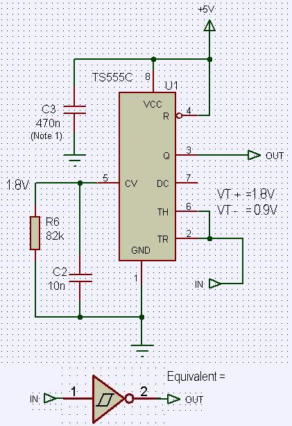
So, closing the loop (to make an oscillator) if the stimulus is offset then we won't get the natural frequency but something close.  And if this offset in stimulus (delay) is temperature dependent (like silicon amplifiers / gates have a tendency to be) then we have introduced an element that will change the frequency of the resulting resonant structure with temperature.  This effect might be somewhat slight, but still an issue seeing as how we are very concerned with ppm (e.g. null point movement).

As I understand it, the Barkhausen Criterion just says that you need a gain of at least 1 from output to input at the resonant frequency, and the resonant period will be equal to the total delay through the loop (or some integer multiple of it including zero).

For LC, we can only limit drive energy so much before the amplitude drops like a rock with external loading and such, so we give it more than it needs to overcome Q loss in order to make sure it starts quickly and operates in a robust manner, but this also means there is excess energy available to drive the oscillator somewhat off resonance if it is so inclined.  So one way to maximize temperature stability is to pick delay elements (L, C, sense & drive) that are relatively insensitive to temperature changes.  If silicon delays are tiny compared to the period then if/when they change with temperature it will be less of an issue.  This could be a reason to use high speed CMOS, particularly if CMOS is already being used and the design can tolerate a faster component.  Or a UHF FET in a 300kHz oscillator.

Posted: 5/28/2014 11:25:34 PM
FredM

From: Eastleigh, Hampshire, U.K. ................................... Fred Mundell. ................................... Electronics Engineer. (Primarily Analogue) .. CV Synths 1974-1980 .. Theremin developer 2007 to present .. soon to be Developing / Trading as WaveCrafter.com . ...................................

Joined: 12/7/2007

Hi Dewster,

Thanks - that's a lovely visual explanation..

you say "This could be a reason to use high speed CMOS, particularly if CMOS is already being used and the design can tolerate a faster component.  Or a UHF FET in a 300kHz oscillator." and I can see that gross delays could cause problems..

But if we take a 300kHz oscillator, and had a phase drift or jitter of say 10ns on the drive, is there a (easy) way to calculate the effect on frequency? - I can see that as the frequency gets higher, the potential for error introduced by phase increases - but is it really of any significance at all down below say 1MHz ?

Hell - im being stupid.. I dont need to do the maths - I can introduce delays in the simulation and let it do the maths for me!

But whatever - I am fairly sure that silicon timing errors probably don't contribute much to noticeable thermal drift in analogue theremins.. I can see however that if one is measuring the period of individual cycles or using higher frequencies for digital purposes, then it could be a problem..

Except that there are so many other 'problems' and causes of variation in theremin circuits, that I would be real surprised if this one even registered!

Fred.

ADDED ->

I inserted a delay on the drive.. Not possible to get results for about <5ns change in delay unless I reconfigure the simulation severely, but get reliable results from 'my' oscillator circuit for an additional 10ns delay..

Much bigger than I expected! - with no extra delay I get 495.070 kHz, with 10ns added I get 495.001 kHz, so about 70 Hz for a 10ns drift.

But 10ns is a long time for silicon.. If this is real, then it doesn't worry me... the 74HC14 has a total propagation delay <15ns..(so even a massive 50% change in propagation delay as a result of whatever, would result in < 50Hz change in frequency)  The bigger possible issue will probably be variation in hysteresis as a function of temperature.. a problem probably less significant with a TS555C, but its propagation delay is much longer (100ns) ... However, I think the TS555C reconfigured by biasing the CV is far more stable than the 40106 or 74HC14.

** UPDATE:

Seems my delay primitive is faulty - it was extending the drive time by 10ns, not acting as a delay.. It seems that actually implementing a delay (shifting the signal by 10ns rather than extending it) through more cumbersome means is giving a much smaller frequency deviation.. But until I find out whats going on with the DSIM its best not to trust any results above).

Oh hell - im not going to look into this anymore now - Ever had that feeling like your going off at a tangent which will lead you nowhere ? well - I usually ignore that feeling -  But not this time ;-) ... Will come back to simulation if I have problems with the real circuit..

In terms of theremins and their environment, I think there is a risk of becoming too fixated on perfect electronic design... How much movement does a player need to do to alter the difference frequency by say 100Hz ? - A tiny realignment of their body does that! ... And how often have I sweated blood trying to get rid of a potential 100Hz drift ? Too often! ;-)

"This effect might be somewhat slight, but still an issue seeing as how we are very concerned with ppm (e.g. null point movement)."

At the show, drift bothered the hell out of me - spot-lamps were moved about, temperatures were changing hugely.. But thinking back on it, it was only when the instruments werent being played - when they came away from null (due to temperature and/or capacitance changes) and started growling at me, that I noticed... When they were being played, there wasnt a problem - as soon as a person approached them, they started making sound.. the player could move their body to get the register they wanted, and play! (or at least make pitch changes and pretend to play ;-) .. Its the bass end where thermal drift is most noticable - but shift the operating point to beyond the null, mute the instrument beyond null, have 100Hz or so of thermal drift in the nulled zone, and mostly everything is fine (I think).

So should we really be so worried about " null point movement." ?

The most important circuit in any one-stick IMO is an automated "wrong side" audio muting circuit - Without this, those bloody instruments would have driven me stark staring mad (rather than just mad) .. It was, by far, my greatest theremin invention!  LOL  .. a way to silence them !!! ;-)

ps - I might be absent for a while... need to spend some time listening to Shepherd tones and watching fractals.... ;-) .. My kids have these horrible RC cars which emit a rising tone when they go forwards and a falling one when they go backwards - but these tones on ramp driven, so reset every couple of seconds... I want sampled Shepherd tones in these, so the pitch always sounds like its going up, or going down, without glitching... Also been wondering about musical application - perhaps in a theremin....... ;-) .. space a few identical octaves on the field, and sweep infinitely in either direction, LOL.. Not much use for playing tunes - but hey, who uses theremins to play tunes ???  ;-)

But what I REALLY want to do is build a L-Frame theremin for Peter - A focused  X-Y field he can wave his trunk in, Y controlling volume, X controlling pitch (or whichever way he prefers)... I want to know if these great wonderful intelligent beasts  have their own music playing in their heads - I want to give them the possibility to express it, and I want to hear elephant music if they do!

Any sponsors for my theremin journey to Thailand ?

Posted: 5/29/2014 3:21:06 PM
dewster

From: Northern NJ, USA

Joined: 2/17/2012

"But if we take a 300kHz oscillator, and had a phase drift or jitter of say 10ns on the drive, is there a (easy) way to calculate the effect on frequency? - I can see that as the frequency gets higher, the potential for error introduced by phase increases - but is it really of any significance at all down below say 1MHz ?"  - FredM

Good question.  Here is a random graph from the web (From: http://www.realworldtech.com/overclocking-realities/3/):

FPGA designers have a bit of intuition regarding this as timing closure results in the tool are presented as corner cases over supply voltage and temperature.  Squinting at the right graph, it looks like 91% speed at -25C, with 100% at 25C, giving 9% / 50C = 1800ppm/C.  Using this figure, if the oscillator loop delay were comprised entirely of logic delay, then it would be stable to 1800ppm/C.  In a parallel LC the drive delay is generally kept to a minimum, in a series LC the delay is either 90 degrees with stiff (low resistance) drive, or 180 degrees with split capacitor and soft (high resistance) drive. 

Note that when the driver is an inverter the 180 degrees of "delay" isn't actually transport or propagation delay.  Also, the temperature above is junction temperature, which tends to be quite a bit higher than package temp or ambient temp.

Anyway, say we use 4069UB inverter as our driver.  The ST data sheet says 30ns typical delay at 10V.  A 300kHz oscillator has a period of 3333ns.  If 30ns of that delay is due to the inverter then it accounts for 30/3333 or about 1%, and 1% of 1800ppm/C is 18ppm/C which doesn't seem too horrible.  Using a lower supply voltage would aggravate things, as would using more than one inverter in series.

I've been pretty aware of delays in my logic based LC oscillators because I generally start with the open loop case (driving the LC with a function generator) where the relative phase of drive and tank (and peak tank voltage) is easily observed on a scope.  This is what moved me away from using large resistances to drop the tank voltage for sensing (to capacitive dividers) as large resistances tend to magnify input capacitance delays.  This is also what moved me away from 4000 CMOS and op amps and other slow fare.

Posted: 5/29/2014 5:46:20 PM
FredM

From: Eastleigh, Hampshire, U.K. ................................... Fred Mundell. ................................... Electronics Engineer. (Primarily Analogue) .. CV Synths 1974-1980 .. Theremin developer 2007 to present .. soon to be Developing / Trading as WaveCrafter.com . ...................................

Joined: 12/7/2007

Interesting stuff, Thanks Dewster -

I will email you my plans soon - I think I could really do with some help on BPF's + phase detection.. In not actually going to be using oscillators much (only one - VFO / HF VCO) - will be driving BPF's from a single fixed Xtal osc, (putting the reference frq into a bunch of BPFs - one tuned to the Xtal osc frequency so that its phase output is used as the reference phase, and will hopefully drift in sympathy with the other BPF's) - then the other BPFs will connect to antennas, and hopefully by comparing phases of the reference BPF against the others I can get CV's to drive the HF VCO (to implement my upside-down topology), volume etc..

My simulations indicate to me that with phase comparison, I dont need a seperate frequency for any of the antennas - it can all run on one master which can be piped to other theremins / equipment - Im looking at a 32kHz "sync" frequency which is stepped up to MO frequency by PLL..

But the whole BPF side has me a bit rattled.. Im much more used to dealing with amplitude rather than phase on BPFs - and I am finding some strange things happening.. Been using series LC, because I want the amplitude - and trying to stick with about 500kHz (>400, < 800) so I can use cheap IFTs.. I am deriving an error signal by comparing the phase of the drive MO to the phase from the reference BPF - hoping to use this for thermal compensation if needed - figuring that if all BPFs are driven in near identical manner their behaviour should be similar and therefore any error signal should give a usable means of correction..

But im floundering a bit..

Fred.

Posted: 5/30/2014 2:37:01 AM
dewster

From: Northern NJ, USA

Joined: 2/17/2012

Hi Fred,

I'd be honored to review your design!  Using a BPF on the reference is something I hadn't thought of but makes sense to match drift. One thing that has stymied me with the upside down approach is a garbling of squared up phase information with a hand on the antenna - things can get a little crazy when the amplitudes drop and harmonics rear their ugly head.  Maybe a broader Q would help?

(I've been contemplating the use of a quasi-upside down left hand for two adjacent antennae, where the amalgam of pitch error is used to alter the common drive frequency and as output of the first axis, and the phase difference between the two is used as the output of the second axis.  Bourns coils seem to be matched closely enough to do this, but IF transformers might work better as they are tunable.)

Eric

Posted: 5/30/2014 3:18:12 AM
FredM

From: Eastleigh, Hampshire, U.K. ................................... Fred Mundell. ................................... Electronics Engineer. (Primarily Analogue) .. CV Synths 1974-1980 .. Theremin developer 2007 to present .. soon to be Developing / Trading as WaveCrafter.com . ...................................

Joined: 12/7/2007

"things can get a little crazy when the amplitudes drop and harmonics rear their ugly head.  Maybe a broader Q would help?" - Dewster

Yeh -

This is where I keep stumbling.. I am using a simple XOR phase detector, and feeding this to an integrator.. Because I want to use the reference frequency to heterodyne with my VFO, and because I dont want any other HF in the machine other than these tw0 (or integer multiple) frequencies, it seems I need really high Q from the BPF's in order to get a reasonable phase change over 8kHz or so..

Ok, I can get away with using amplification, but I dont want to.. Also, theres an upper and lower 'knee' in the phase change which I would really like to use for linearity correction - Oh, I dont "need" to - I could use the linear region and analogue shaping pre-VCO (and pre-VCA) , but if I can get good enough linearity correction without that, all the better! I want the maximum phase change over as small a frequency span as I can get - if I could encompass most of the 'squashed down S' phase curve in 6kHz that would be ideal - but to do that I would need to go above 1MHz - or have higher Q than I am managing at present - I dont really like either option.

I have had the most frustrating day with my simulator - its crashing every few minutes.. But one area I am exploring is trying to simulate the 'antenna-person-antenna' interactions - Not really sure how to do this - been using a 'Y' capacitor network, 100pF to ground, and a few pF from the node to each antenna.

I am driving the hell out of my BPF's (sine currents in the inductor between 20mA and 100mA P-P depending on what im playing with in terms of Q) and am loading the antenna with 100kR into the phase comparator clamping diodes, but still getting 120V P-P on the antennas (This certainly doesnt qualify as an entry for your low power contest, LOL ;-)..

But I havent seen any interaction - However, my simulator might be trying to show me something so horrible that it bombs out in fear! ;-)

Fred.

 -- And all the time I am asking myself.. Why the hell am I back here? WTF got me to return to theremin stuff ? I was nicely slipping into audio post-processing for the EW and sensible things like audio formant filters - and on the side doing my C-Ribbon... But here I am, back with this bloody weird HF LC crap!

and while I do this, someone somewhere may have read my formant ideas, built the bloody thing, and bring it to market to huge acclaim! LOL ;-) .. I need a technician who will work (like me) for nothing, and build the damn things..

AAARRRGGGghhhhh!

Posted: 5/30/2014 4:02:12 AM
FredM

From: Eastleigh, Hampshire, U.K. ................................... Fred Mundell. ................................... Electronics Engineer. (Primarily Analogue) .. CV Synths 1974-1980 .. Theremin developer 2007 to present .. soon to be Developing / Trading as WaveCrafter.com . ...................................

Joined: 12/7/2007

Dewster,

Do you know of any nice TH packaged push-pull drivers? I have used Micrel MOSFET drivers in the past, and am looking at the Microchip TC4469 http://ww1.microchip.com/downloads/en/DeviceDoc/21425C.pdf

but ideally I dont need so much current +/- 200mA / Drive max, and the ability to control the output high level would be real nice (or take VCC down to perhaps 2V7 rather than 4V5).. And be fast.. I dont mind having extra current available obviously, but am sure there must be something perhaps not intended as a driver, which will do the job better..

Fred.

Posted: 5/30/2014 10:00:38 PM
FredM

From: Eastleigh, Hampshire, U.K. ................................... Fred Mundell. ................................... Electronics Engineer. (Primarily Analogue) .. CV Synths 1974-1980 .. Theremin developer 2007 to present .. soon to be Developing / Trading as WaveCrafter.com . ...................................

Joined: 12/7/2007

Dewster -

On re-reading your idea 5/28/2014 4:44:03 PM FSK/MSK HV switched L oscillator in the "crazy" thread (rather than imposing my crap on it) I think it might be workable - not sure about changing the inductor value (could you have a tapped inductor in a series LC, and switch the drive side to one or other tap at a point when the inductor is uncharged?) but I think some way of changing frequency on a cycle-cycle basis with minimum loss should be possible.

And perhaps the idea of heterodyning isnt completely trashed.. If the VFO switches synchronously with the MO..

Having one fixed invariable antenna frequency (as I am proposing) common to both pitch and volume hasnt, as far as I know, been done before for theremins.. (fixed frequency into C controlled BPF has been, as with the EW and many others for volume) ... Fixed Frequency Volume antennas using amplitude variation to derive CV are, IMO, one of the biggest sources of interference into the theremin from outside radiators..

My scheme may not work - It certainly wouldnt work if I was looking at amplitudes - but I believe that if I keep the antenna amplitudes high enough under maximum load conditions, phase detection will work.. Not sure yet which is better, whether to flip the 2 antenna drive phases 180 degrees to each other, or keep them at 0 degrees - But it looks like 0 degrees is the winner out of those.. (180 degrees has an advantage of reducing total radiated emission levels though).. I also wonder about say 90 degrees (shift in the drive phases)  and limiting the phase detection to < 1/2 of each half cycle, comparing against the ZC of each waveform.. this should (?) move any possible interactions between the waveforms away from each other (?).

If the above doesnt work for some reason I havent yet discovered or thought of, I may have a "fallback" .. The same hardware could alternately drive one BPF (antenna) then the other - a few cycles alternatively to each, with enough settling time between them (Say a total excitation / settling time for each of perhaps 50us  or perhaps less - some switching frequency way above audio)  , and the phase data for each could be captured - Even heterodyning would still work, as I dont need to interrupt the MO, and the VFO (and VCA) would be driven from the derived data..

(not sure if it was you who floated the idea of switching antennas - but I don't think I originated it)


If spread spectrum could be added simply, regardless of which scheme was used, that would be a nice extra feature!

Fred.

Posted: 5/30/2014 10:53:34 PM
dewster

From: Northern NJ, USA

Joined: 2/17/2012

"And all the time I am asking myself.. Why the hell am I back here? WTF got me to return to theremin stuff ? I was nicely slipping into audio post-processing for the EW and sensible things like audio formant filters - and on the side doing my C-Ribbon... But here I am, back with this bloody weird HF LC crap!"  - FredM

You're doomed.  I think Theremin R&D reduces one at some point to an almost endless, reflexive search for "something better" in terms of oscillators / sensors / whatever.  If I didn't have a strong side pursuit (Hive) it probably would have driven me crazy long ago.

"Not sure yet which is better, whether to flip the 2 antenna drive phases 180 degrees to each other, or keep them at 0 degrees..."

As you say, 180 degrees will maximize interaction and minimize emissions.  0 degrees vice versa.  I suppose it depends on whether your arrangement can easily handle the added interaction to be able to "spend" it on reducing emissions.

"(not sure if it was you who floated the idea of switching antennas - but I don't think I originated it)"

I'm not sure I've seen it here at TW.  I personally first encountered it on a 3D mouse web page (or some such, will try to locate it). [EDIT] Can't seem to find it.  They were using multiple LC sensors, stimulating them in turn, for multiple cycles (long enough to establish sufficient amplitude, run it for a bit, then enough time for the oscillations to die down).

I wonder why I keep looking for different modulation / demodulation schemes.  Frequency division seems like it works pretty well.

Posted: 5/31/2014 12:14:25 AM
FredM

From: Eastleigh, Hampshire, U.K. ................................... Fred Mundell. ................................... Electronics Engineer. (Primarily Analogue) .. CV Synths 1974-1980 .. Theremin developer 2007 to present .. soon to be Developing / Trading as WaveCrafter.com . ...................................

Joined: 12/7/2007

"I wonder why I keep looking for different modulation / demodulation schemes... " - Dewster

LOL ;-)

We both know there are a few things nobody has thought of (or at least shown anyone) yet - some wonderful things that a random spark between two random neurons could reveal.. (or sometimes all it takes is a few synergistic engineers bouncing ideas off each other ;-)

Less chance of ever having such a thing happen than winning the lottery - but hey, if you dont buy a ticket you have no chance of winning the lottery! ;-)

Anyway - just to brighten this thread up with some horrible colors, this is my "fallback" plan in rough.. Thinking that I read the phase a few us after stopping the drive, so that the BPF's natural resonance is detected.. perhaps doing the sequencing / sampling closed-loop so levels are all stable (above / below trip points) when the states are changed (could also actively damp the resonator after phase data is collected, to speed up the operation)

Probably be a lot easier to do all this stuff digitally with an FPGA or whatever driving the BPFs and sequencing based on data from a less complex AFE than doing it all analogue - I would be forced to add a digital sequencing board if I wasnt able to get good enough resolution driving the antennas continuously - and I am designing 'hooks' into my analogue board/s to allow this to be added if needed... or will be ... havent got to board layout yet - havent even prototyped many of the essential bits - its mostly in my simulator.

Fred.

You must be logged in to post a reply. Please log in or register for a new account.