Let's Design and Build a (mostly) Digital Theremin!

Posted: 10/12/2018 8:45:52 PM
pitts8rh

From: Minnesota USA

Joined: 11/27/2015

I seem to remember that you told me that you had (or could easily have) an unmodulated audio signal point available for an optional pitch preview circuit.  Is that correct?

With that available I would just add an analog VCA waveshaper for PP.  I would prefer that this be under potentiometer control anyway, not encoders and menus.  Not everyone needs pitch preview, but those that do may not even consider a theremin that doesn't have it.

I used to think that fast visual tuner would be a huge benefit for the theremin.  For that reason I like to use the spiral display in SpectraTune for Windows.  It was fast, and it had the easily recognizable circular scale, similar to yours except it was continuous.  Don't get me wrong, I still think the visual tuner of some sort (I like a fast waterfall) is a useful feature, especially if you do not use pitch preview.  But I still stick by the argument that relying on a visual feedback loop to control pitch is much, much slower than using auditory feedback (many brain cycles slower, whatever your particular brain clock speed is). 

On top of that, if voltages were made available (or outputs for DACs) that are at least roughly proportional to pitch (doesn't need 1v/octave compatability) and volume, I would be ecstatic.  The volume voltage can be conditioned to make PP volume level controllable with theremin volume (either sensing, including inverted ala Subscope), and the pitch voltage can be used to lower PP volume with increasing pitch, something I currently have to do with an external 2-pole LPF just to keep perceived PP loudness fairly constant with pitch.  Having a pitch-proportional voltage available lets you control the PP VCA with any slope you want.  I always have a problem with pitch preview in that you set the volume barely loud enough to be able to perceive low notes and it ends up screaming in your ear at higher pitches.

And while I'm making my Christmas Wish List, lets build in a constant-tone switchable output available for the pitch preview earpiece.  Just like a chromatic guitar tuner's tone output (which is what I use now), except built right into the theremin.  This is for those of us that tend to wander off scale without any accompaniment (and close our eyes while playing, so that we wouldn't see a tuner anyway..).  You just play theremin with a constant pitch tone droning in your earpiece.  It takes a little getting used to, but if you can sense relative pitches just fine but not absolute pitch, it acts as a constant reference.  For me I find that it doesn't matter what pitch the drone note is at, as long as it is audible.  It seems to make any note in the scale just light up when you play on pitch.

This is useful if you would like to record a theremin piece at your own pace and add accompaniment later.  Or if you want to perform a piece without any accompaniment without wandering out of your lane and into the ditch.  It's like a little tuner in your brain, if you aren't gifted with the real thing.

For a while I thought that playing with a drone tone it was just something that I fell upon, but of course I looked it up and apparently it is a thing.

Anyway, I got off on a rant there, but pitch preview - gotta have it.  Or at least some unmodulated audio for DIY PP. Gotta gotta.     

Posted: 10/12/2018 9:24:45 PM
dewster

From: Northern NJ, USA

Joined: 2/17/2012

"I seem to remember that you told me that you had (or could easily have) an unmodulated audio signal point available for an optional pitch preview circuit.  Is that correct?"  - pitts8rh

Absolutely.  The SPDIF converter box is stereo, and the SPDIF register in Hive that feeds the SPDIF logic is also stereo.  At the moment, for lack of anything better, I'm just slapping the same mono signal into both PCM slots.  One could easily add more FPGA logic and register set interface, and feed more SPDIF boxes if it came to that.

(When reading up on analog string filters you mentioned, one design routed every other bandpass filter to L & R with a stereo spread control, which has got me thinking something like that might be easy to do with the non-harmonic resonator; I'd love to get some kind of synthetic stereo going.  But I digress...)

"With that available I would just add an analog VCA waveshaper for PP.  I would prefer that this be under potentiometer control anyway, not encoders and menus.  Not everyone needs pitch preview, but those that do may not even consider a theremin that doesn't have it."

What would this "waveshaper" do exactly other than VCA?

The main UI page is full, but something could be moved (such as a duplicate of the volume axis null which I never really use) to make room for pitch preview control. There's a master volume control on there now that works quite well via the generic encoder input.

"Not everyone needs pitch preview, but those that do may not even consider a theremin that doesn't have it."

Good point!  And I hope you don't think my ~rant in the previous post was aimed at you, it wasn't.  I like to think I'm really not out here to try to change player's minds or twist their arms over things they like / want / need, but offering them higher quality versions of what they already have, plus some key extras.

"I used to think that fast visual tuner would be a huge benefit for the theremin.  For that reason I like to use the spiral display in SpectraTune for Windows.  It was fast, and it had the easily recognizable circular scale, similar to yours except it was continuous.  Don't get me wrong, I still think the visual tuner of some sort (I like a fast waterfall) is a useful feature, especially if you do not use pitch preview.  But I still stick by the argument that relying on a visual feedback loop to control pitch is much, much slower than using auditory feedback (many brain cycles slower, whatever your particular brain clock speed is)."

Any time lag here is probably deadly, and it's hard for me to believe things that have to do FFT analysis or period measurement or auto-correlation aren't somewhat laggy.  Well, if nothing else it will be interesting to see what you think of the effectively instantaneous display on the prototype.

"On top of that, if voltages were made available (or outputs for DACs) that are at least roughly proportional to pitch (doesn't need 1v/octave compatability) and volume, I would be ecstatic.  The volume voltage can be conditioned to make PP volume level controllable with theremin volume (either sensing, including inverted ala Subscope), and the pitch voltage can be used to lower PP volume with increasing pitch, something I currently have to do with an external 2-pole LPF just to keep perceived PP loudness fairly constant with pitch.  Having a pitch-proportional voltage available lets you control the PP VCA with any slope you want.  I always have a problem with pitch preview in that you set the volume barely loud enough to be able to perceive low notes and it ends up screaming in your ear at higher pitches."

Slowish (less than audio sample rate but fast enough to control your VCA) DC voltages should be doable with a delta-sigma DAC logical construct in the FPGA and some external analog filtering.  But all of what you describe above would be pretty easy to do via DSP inside the FPGA.  I'm hoping we can perhaps help each other develop this to your satisfaction.

"And while I'm making my Christmas Wish List, lets build in a constant-tone switchable output available for the pitch preview earpiece.  Just like a chromatic guitar tuner's tone output (which is what I use now), except built right into the theremin.  This is for those of us that tend to wander off scale without any accompaniment (and close our eyes while playing, so that we wouldn't see a tuner anyway..).  You just play theremin with a constant pitch tone droning in your earpiece.  It takes a little getting used to, but if you can sense relative pitches just fine but not absolute pitch, it acts as a constant reference.  For me I find that it doesn't matter what pitch the drone note is at, as long as it is audible.  It seems to make any note in the scale just light up when you play on pitch.

This is useful if you would like to record a theremin piece at your own pace and add accompaniment later.  Or if you want to perform a piece without any accompaniment without wandering out of your lane and into the ditch.  It's like a little tuner in your brain, if you aren't gifted with the real thing.

For a while I thought that playing with a drone tone it was just something that I fell upon, but of course I looked it up and apparently it is a thing."

That's quite interesting!  How bright should this drone be (e.g. can it be a sine wave?)?  Regardless, it should be straightforward to add this option.

Posted: 10/12/2018 11:02:36 PM
dewster

From: Northern NJ, USA

Joined: 2/17/2012

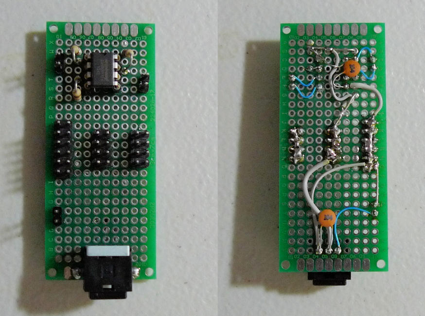
The Hardwareing: SPI EEPROM / TOSLINK TX / Power Distribution

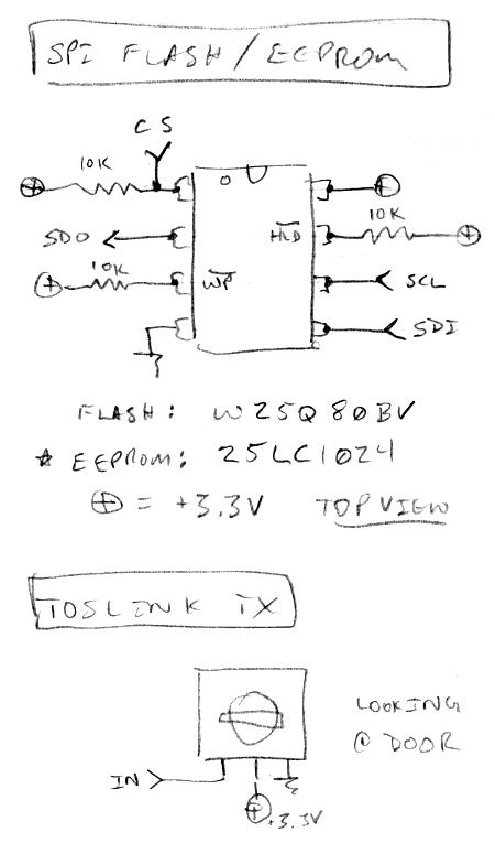
When I initially built this board I stuck a SPI Flash part (W25Q80BV) on it.  The part was quite fast (I was clocking it at 50MHz) but the mandatory erasing of large swaths was burdensome, and the write cycles somewhat limited.  So I swapped it out for a SPI EEPROM part (25LC1024).  It runs slower at 10MHz (had to change the SV and recompile / repump the FPGA to accommodate that) but it uses the same codes and procedures for reading and writing, and I can't say I notice any difference in terms of boot times.  Probably the best thing about this EEPROM is you don't have to erase it to reprogram it, you can overwrite a single byte in a page and the rest of the data remains, and it's reprogrammable at the 256 byte page level, rather than the 4KB block level of the Flash part.  It's quite a bit smaller, but entirely adequate for this purpose.

I figured the TOSLINK TX was just an LED in a box, but there is an active driver in there.  3V to 5V supply, with buffered input that is easy to drive.  It drives so easily (high impedance) you can see the LED inside lighting up with coupled 60Hz hum from your finger.

Also on this board are three groups of power distribution headers, basically all the pins in a group are soldered together (except when they aren't but look like it - fun bug).  This is the power pickoff point for the EEPROM and TOSLINK.


That's the SPI EEPROM chip at top, power distribution headers in the center (L-R: GND, 3.3V, 5V), and TOSLINK module at the bottom.  If I were to do this again I'd add more pins to the distribution headers, particularly the ground, maybe 16, as I ended up running a bit short.  Both actives are bypassed via 0.1uF ceramic caps.


Not a lot to say about the schematics here, really simple.

Posted: 10/12/2018 11:06:39 PM
pitts8rh

From: Minnesota USA

Joined: 11/27/2015


What would this "waveshaper" do exactly other than VCA?

It allows you to change the timbre of the pitch preview,  which helps with audibility under different conditions, such as if you fully plug the ear with an earpiece, leave the ear partially open, or use other monitoring as I do.  On my frankentheremin I have simply replicated the Etherwave's LM13700 VCA with the brightness and waveform controls. This gives two identical audio paths - one modulated by the volume loop and the other fixed or modulated differently to enhance the PP effectiveness. You can simply adjust the PP gain via a pot for volume, or you can sum in other bias voltages (easy with the CV board on the plus model) to modulate the PP volume as described above.  I meant brightness and waveform when I said wave shaping.

That's quite interesting!  How bright should this drone be (e.g. can it be a sine wave?)?  Regardless, it should be straightforward to add this option.

I think a sine would work, but maybe a little brighter tone with both even and odd harmonics would be better.  The tuner I use that generates a tone has a square wave output, which is not the best but still quite effective.  I would think you could variably sum it right in with the pitch preview chain, although having separate control of the timbre of the drone tone might be key to keeping them separated in your head.  It might seem that having two tones would be confusing, although I really don't experience a conflict, but again, my drone is a nasty square wave, and maybe that is helping to avoid confusion..  Your brain sort of acclimates to the drone, and after a couple minutes you hear normally "around" it.  When you turn it off you really feel like something has been burned into your brain though.  Like retinal fatigue.  I'm sure there is a term for it.


If you have something to generate a tone near your theremin, give it a try.  There are online drones that you can practice to as well.

Posted: 10/12/2018 11:38:50 PM
dewster

From: Northern NJ, USA

Joined: 2/17/2012

The Hardwareing: Rotary Encoders

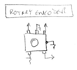
It doesn't get any simpler than this (FPGAs were made for this kind of thing, lots of pins, programmable pullups, customized high speed conditioning):


The center pin of the rotary encoder side (top here) is grounded, and the other two pins sent to the FPGA, where they are given a weak 3.3V pullup, debounced, decoded (Gray code => binary code via a counter-based state machine), and sent to a Hive register.  Similarly, the pushbutton side (bottom here) has one pin grounded and the other sent to the FPGA, where it is weakly pulled up, debounced, and sent to the same Hive register.  Hive software samples this register at 48kHz and accumulates it.  This data is then resampled at the LCD update rate, and velocity calculated to make fast knob spins give larger values.  It's interesting that, the way things are set up, the mere sampling of the pushbuttons debounces them.

There are 8 encoders, located below the LCD display, in 2 columns / 4 rows to directly correspond to the parameter data entries on the LCD.  Vertical interspacing is ~30mm, horizontal interspacing is ~39mm.  You want enough room here so you can spin the knobs easily without interference.  The horizontal interspacing could probably be reduced a bit from ~39mm without causing interference, but the vertical combined will probably be more of a limiting factor for the controls enclosure if you use anything smaller than the specified plastic shoe box.

Note the case of the encoder is grounded, this helps keep ESD, a very real thing on something like this that gets touched a lot, from making its way to the FPGA, which could be kinda bad.  Before I grounded them I noticed ESD events pushing the processor off the rails.

You could panel mount the encoders and wire them in the air, or put them 2 or 4 to a board, whatever makes the most sense.  I have 6 on one board and 2 more on another board, which is a historical thing rather than planned (the encoder count grew several times during development).

I don't think there is an electrical / mechanical standard for the rotary side of these things?  IIRC, the ones I bought from AdaFruit (not recommended) had the opposite CW / CCW sense on the pins than the cheap Chinese ones I bought (recommended).

OK, I think all that's left is the FPGA board pinout.

Posted: 10/13/2018 5:46:32 PM
dewster

From: Northern NJ, USA

Joined: 2/17/2012

The Hardwareing: FPGA & LCD

The FPGA board is a WaveShare CoreEP4CE6 I bought off eBay.  Schematic is here: [LINK].  The board has two banks of pins on each side, which I connected to the other boards in the prototype via short (100mm) and long (200mm) "Dupont" "Arduino" female-to-female jumpers.  The jumpers came connected together as a rainbow ribbon cable, but I pulled them apart to yield individual jumper wires.  Individual wires reduces crosstalk between jumpers, and may also improve signal integrity from an impedance standpoint.

The most accurate pinout is necessarily in the "ep4ce6e22c8_demo_board.qsf" file, a Quartus Settings File, which tells the Quartus tool how to assign them, among other things.  Altera makes Excel spreadsheets with pinout info for all their parts, and I like using these as I find it easier and more systematic to micromanage and generate the *.qsf file myself (it is a text file).  

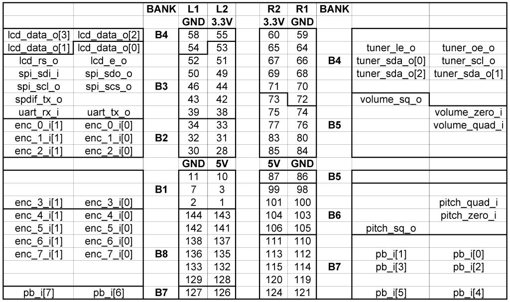
I made another spreadsheet that shows more graphically where the jumpers go, which helps when actually doing the jumpering: [LINK].  Here's a view of that:

This is a view looking at the pin jumper side of the board, which is actually the backside.  The FPGA signal naming convention here is inputs have "_i" appended and outputs have "_o".

Connect the USB TTL serial bridge serial data wires to uart_rx & uart_tx.  Connect the USB TTL serial bridge power wires to GND and 5V.  This provides power to the prototype, and provides serial communication between it and the host PC.  3.3V is a regulated output of the FPGA board, run it and 5V and ground over to their respective power & ground distribution headers on the SPI EEPROM / TOSLINK TX board.

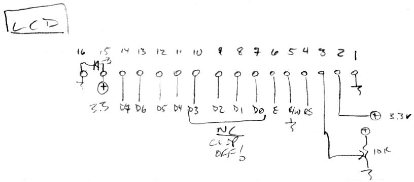
The LCD hookup goes like this:

I soldered a row of pins to the back of the LCD to accommodate jumper wire hookup.  The data hooks up D4 through D7 on the LCD, with the lower nibble unused, so I snipped those pins off.  I used wire wrap wire to run the ground from pin 1 over to pin 5 and pin 16. Similarly, I ran +3.3V from pin 2 over to pin 15.  The contrast pot I used is actually a 22k linear miniature screwdriver type (what I found in the junk box, works fine) that I mounted on the front of the LCD (physically and electrically by soldering the pot lugs to LCD pads), with access via a hole drilled in the enclosure.  The white LED backlight has an internal current limiting resistor scaled for 3.3V.

OK, other than the ESD bleed pad I showed earlier here [LINK] I think that's pretty much it for hardware documentation.  Y'all let me know if I missed something, or if anything seems too ambiguous.

The prototype hardware is pretty simple because 90% of the complexity is captured by digital constructs in the FPGA and the Hive firmware.  A good rule to live & design by: do the absolute bare minimum in analog, and the rest in digital (logic & code).  This yields the lowest construction complexity & cost, and the most stability & flexibility (particularly when an FPGA is in the mix).

Posted: 10/14/2018 8:50:44 AM
pitts8rh

From: Minnesota USA

Joined: 11/27/2015

It's good to have most of the current build information and links in one spot.  I've edited this down to only your posts and printed it all into a bench manual so I don't have to keep referring to a tablet or computer while they are generally preoccupied with something else.

Maybe I've missed it, but do you have a block diagram or photo of the FPGA, eeprom board, toslink, and power source assembly?  Your pinouts above generally give the information, but at this stage I'm still trying to get a quick overall picture for logical physical package and PC board layouts.  As I said earlier, although I want to minimize variations from your functional design initially until everything is working, I see no harm in trying to evolve the physical design a bit where practical to make it one step closer to an easier DIY project.  Another photo or a few would help me fill in the gaps.

Otherwise this is an excellent compilation to have in one place.  It was probably hard to stop what you were doing to draw this all together, but now you have another very important key topic for your index (which I've lost, BTW).

One more thing...  How stable (design evolution-wise, not functionally) is the oscillator board/inductor combination?  I want to try doing a quick oscillator board layout, and I'm wondering if you would recommend any extra pads or circuit options (tuning elements) for the board?   I'm still waiting on parts, but I'm nearly ready to start winding coils and making oscillator boards.

Roger

ON EDIT: a second one more thing - approximate plate dimensions?  I won't be using the plastic boxes for reference, so I need to know a starting place for the plates.  They will no doubt be somewhat different without the plastic, but knowing your sizes would help.

Posted: 10/14/2018 3:22:44 PM
dewster

From: Northern NJ, USA

Joined: 2/17/2012

"I think a sine would work, but maybe a little brighter tone with both even and odd harmonics would be better.  The tuner I use that generates a tone has a square wave output, which is not the best but still quite effective.  I would think you could variably sum it right in with the pitch preview chain, although having separate control of the timbre of the drone tone might be key to keeping them separated in your head."  - Roger

All harmonics (both even and odd) are very doable, IIRC this only requires a single SIN2 calculation via the oscillator I'm using.

"Maybe I've missed it, but do you have a block diagram or photo of the FPGA, eeprom board, toslink, and power source assembly?  ... Another photo or a few would help me fill in the gaps."

There are a couple of pictures in the thread showing the empty prototype, the plywood stick and CCTV camera mounts (lame, don't use), and the internal wiring.  I put a big bold PIX indicator next to these (and others) in the index.  But I'll take a few more and post them soon.

"... your index (which I've lost, BTW)."

The index is located in the very first post to this thread.  Go to the top of this page and click on the "First" button to get there quickly.

"How stable (design evolution-wise, not functionally) is the oscillator board/inductor combination?  I want to try doing a quick oscillator board layout, and I'm wondering if you would recommend any extra pads or circuit options (tuning elements) for the board?"

Very stable (famous last words), though of course the ESD protection hasn't been tested at all.  As I stated in the AFE post, I would probably route 3 of the extra unused ESD protection pins to the cable I/O (there are 6 protection circuits in the IC, with 2 currently in use).  Bypassing the ESD chip power pins with 0.1uF would be good.  And I would probably put extra pins or pads next to the strip of 3 pin sockets used for the 1pF / ~100pF capacitive divider caps, just so you could solder everything once the antenna is done and after the ~100pF value has been adjusted so as to not to clip.  [EDIT] Oh, and I would definitely put a CAT5 connector on there.

"... approximate plate dimensions?"

Ah yes, thank you.  

Both are 6" (~150mm) wide aluminum flashing from Home Depot, held to the case via a nylon screw and nut, which also affixes the coil in the center.

The pitch antenna is as large as will fit in the given enclosure bottom: 6" x 300mm (0.045 m^2).
The volume antenna is as large as will fit bent in the given enclosure: 6" x 200mm (0.03 m^2).

[EDIT] Antenna plate area is the main thing, and if I had the option I probably wouldn't bend the volume antenna plate.  Antenna shape is pretty non-critical - on paper, a square or circular plate should give you ever so slightly better linearity than a rectangular plate - but in practice, I very much doubt that a person would be able to detect the difference.  Linearity on the volume side is important, linearity on the pitch side is very, very important.  

Also, I've noticed that I tend to dial the axis parameters in so that my left hand never gets very close to the volume antenna, maybe 6" minimum here, anything less feels vaguely dangerous / uncomfortable. When playing the cello voice I sometimes have my right hand almost touching the pitch antenna when playing the upper register (I use the octave bank switch when doing this a lot so as to avoid the closeness).  I've also found that, while playing some distance from the pitch antenna is entirely linear, it feels more comfortable to play nearer to the pitch antenna - but not too near, maybe a foot or so away feels like the sweet spot.  I don't know if that's just me practicing there a lot (muscle memory), or the increased influence of my body C over linearity in the far field (a thing no matter what linearization scheme is employed), or what.

Posted: 10/14/2018 4:27:38 PM
pitts8rh

From: Minnesota USA

Joined: 11/27/2015

Listen to these drones - they sound like an organ. FWIW, I don't need to change the tone's pitch for different music.  No matter what key I'm playing in, the single constant pitch helps act as a reference:
https://fiddlerman.com/fiddle-learning-tools/drones-for-intonation-practice/

For ball swivels, I have an idea I want to try before mention it, but it doesn't involve any commercial mounts.  There are actually a couple fairly simple options for this.

And I just received RJ-45 connectors today for the oscillator boards.  But today I'm casting parts for the Melodia, so I won't get any Dewster Theremin work done.

Have you come up with a name for this yet?

Roger

.

Posted: 10/14/2018 5:06:59 PM
dewster

From: Northern NJ, USA

Joined: 2/17/2012

"Listen to these drones - they sound like an organ. FWIW, I don't need to change the tone's pitch for different music.  No matter what key I'm playing in, the single constant pitch helps act as a reference:"  - Roger

Thanks for that!  I watched his video and downloaded the A drone MP3.  In Audition I see the A3 harmonic series 220, 440, 660, 880, etc.  I also see the E4 harmonic series 330, 660, 990, 1320, etc.  There are strong harmonics past 10kHz.

"And I just received RJ-45 connectors today for the oscillator boards."

Could you give a link to the part?

"Have you come up with a name for this yet?

The Walther Wallin PK380 - just kidding!  No name yet, I'm open to suggestions.  I suppose it needs "ether" or "aether" or "aeiouther" or "vox" or "wave" in it somewhere.  xtheremin8 called it my "tupperware-party" which always gets a laugh!  I wonder if the Subscope is so named because it sorta looks like a submarine with the scope up? 

You must be logged in to post a reply. Please log in or register for a new account.