Let's Design and Build a (mostly) Digital Theremin!

Posted: 2/28/2020 6:50:05 PM
dewster

From: Northern NJ, USA

Joined: 2/17/2012

Shemale

The new PV_FMOD controls are really improved, much more intuitive and useful, and so finally worth the one full UI page they consume.  I borrowed heavily from the volume knee code and then tuned it a bit.  It speeds coding up greatly if you have proven boilerplate elsewhere in your design.  Here is the axis transformation:


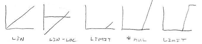
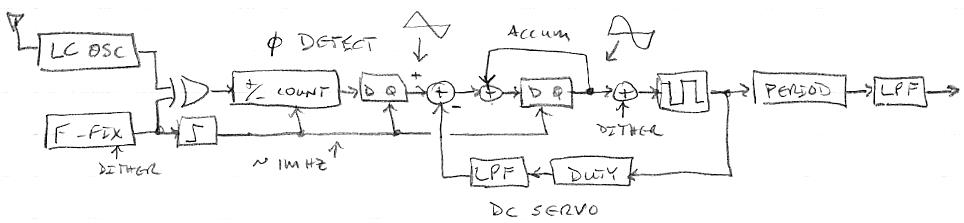
The linear axis number range is shown at left.  From this we subtract the Vloc or Ploc knob value (the knob value is left shifted to make it full scale, then offset to cover the range [0.75:1), or 48dB in linear axis space).  This is limited to lop off the negative values, then shifted right twice to divide by 4 (not shown, this gives mul more low end range), then multiplied up by Vmul or Pmul (the knob value is squared to extend the dynamic range), then limited again to lop off values too large to fit in the 32 bit integer register space as an unsigned value.

The above is used to modulate the various filter cutoff frequencies in the D-Lev.  There are separate enables for the oscillator filter, the noise filter, and the formant filter bank (of which 4 out of 8 are modulate-able).  When enabled, the PV_FMOD takes the place of the more general PVmod mechanism which is fed to everything else that can be modulated via the axis numbers.  PV_FMOD allows us to quite sharply change filter frequencies: if Pmul is to maximum, one can do an entire filter sweep from subsonic to the maximum of A8 or 7040Hz over the range of less than one half note step.  Ploc sets the location for this change, above which the change takes place.  One can also do much milder modulation and / or over much wider note / volume ranges if so desired.

Here is a male voice preset being modulated with both axes via PV_FMOD, followed by an example of the step-like filter frequency sweep over the full range: [MP3].  Playing the step slowly (hard to do!) sounds like we're tuning a radio, playing it quickly sounds like "blips".  The sound itself is a high Q filter stimulated by noise, giving us a sine wave.

Here is a male voice preset morphing to female with increasing pitch, via formant modulation, first with the blend being over approximately one octave, then more abruptly over the range of less than half a step: [MP3].  I thought this would be more interesting / spooky, but it's just goofy.  Not sure if one could find a real use for it.

These are rather extreme examples of what it can do, one would probably use it more to change vowels subtly and slowly.

[EDIT] Corrected errors in the axis transformation text.

Posted: 3/1/2020 5:16:29 PM
dewster

From: Northern NJ, USA

Joined: 2/17/2012

AaahhOOOooo(Gaaa)

A female vocal morphing from Ah to Oo over an octave or so range: [MP3]

A 2-axis volume side would be well suited for this kind of stuff.

Posted: 3/2/2020 2:18:54 AM
dewster

From: Northern NJ, USA

Joined: 2/17/2012

"My thought isn't original and coincides with opinions of professional thereminists:  constantly looking at the tuner is not only useless, but also harmful for playing in tune." - ILYA

I can't say I'm coming at playing the Theremin from a position of knowing it well enough to play it even passably before I had a sufficiently responsive patterned tuner, so take this with a grain of salt (and the following isn't intended as a plug for my own stuff or a knock at others).  The Theremin was (and still is) absolutely fascinating to me from a physics standpoint, but my EW was honestly something of a let-down in the music department.  I could play a recognizable phrase or two on it, but I basically put zero time into learning the thing because it just didn't inspire me at all (probably a failing on my part).  The Theremini was more fun initially, but the untrimmable v1.0 SW calibration procedure mostly precluded musical playing on it, so once I was past the "woo-woo" trying out all the presets point, I was pretty much over it.

Relying on a tuner may be rather like watching one's fingers when learning how to touch type: it can speed things up initially but will impede one's later progression (speaking from personal painful experience here with the typewriter).  Pitch correction is yet another thing that I don't think I would want to do without, as it improves my sloppy playing technique, and allows me to indulge in pieces that would sound rather worse without it.  And if one is using pitch correction, then one must know where the pitch is in an absolute sense at all times in order to not have it fight one and introduce further error.  So watching the tuner is rather mandatory when pitch correction is engaged - it's a package deal.

Are pitch correction and the tuner crutches?  Will the wider note spacing I'm using (~3x normal) turn on me at some point?  Will I eventually rue the day I ever decided to use these things?  Will they then take forever to unlearn?   Who can say, but I'm really 100% OK with them at this point, and they largely enhance my personal enjoyment of playing the Theremin.  But what this all means in the larger scheme of Theremins is probably nothing, as we all have our own little ways.  Anecdata...

[EDIT] To continue with ILYA's positives:

"Nevereless it is still useful for:
1. Adjusting after production.
2. Soundless tuning before performance.
3. First note search.
4. Finger position trainings.
5. All kinds of checks (linearity, thermal drift an so on).
6.(Maybe) ear training."

1. This applies to the D-Lev as well, the axis processing numbers have to be set after the thing is constructed.
2  This is also something I do on the D-Lev, I press the autocal button and check the tuner for proper note spacing in the far field (same as adjusting pitch & volume null on an analog Theremin).
3. This is absolutely critical IMO, particularly when playing without accompaniment.  One of the main issues I had with the EW was I didn't know where to start a song out.  Now that I've got a bit of muscle memory built up I really rely on it for playing, and the least little thing throws it "out of calibration", so at this point I really, really need to know where to start a song that I already know how to play.  There's a good reason Theremin included a (single note) tuner on some of his models, and many pros have a guitar tuner or similar permanently attached to the line-out.
4.  This is something I use the tuner for too, though it's more arm / hand.  And since I use the tuner continuously, it's real-time training rather than off-line.
5.  This also applies to the D-Lev, drift mostly affects the far field, and thus linearity there, so if the far field note spacing is off there has been some drift, or my body has moved some, etc.  And the tuner is essential to setting the near field linearity knob, it would be a gigantic pain to adjust otherwise.
6.  The more you play in tune, the more your ear gets trained to hear good pitch.  If a tuner has a high precision display (e.g. PWM) then it can provide direct and detailed pitch feedback.  Pitch correction is also part of this, as it forces you to hear more notes as perfect (if you set it to absolutely correct).

Can you just plug a guitar tuner into an EW and get all of these benefits?  Volume side obviously no.  Pitch side partially, but much is lost due to high latency (if you can't rely on it to know where the pitch is RIGHT NOW! then you can't use it actively during play), and the lack of regular, easy to recognize patterns on the tuner (you can't afford to waste any brain cycles figuring anything out on the tuner, it has to be absolutely as intuitive as possible).

Posted: 3/2/2020 3:22:45 PM
ILYA

From: Theremin Motherland

Joined: 11/13/2005

Verdict is "Must Have"!

Posted: 3/2/2020 3:33:26 PM
dewster

From: Northern NJ, USA

Joined: 2/17/2012

"Verdict is "Must Have"!"  - ILYA

Yay!  I'm going to dub the tuner on the D-Lev Active Tuner(TM) (or maybe "Dynamic Tuner"?) as it can be used for real-time playing feedback (for better or for worse...).

Posted: 3/2/2020 11:35:37 PM
dewster

From: Northern NJ, USA

Joined: 2/17/2012

Heterodyne => Phase Difference => Integrate => Period Measurement

ILYA's use of a switched capacitor filter construct to do heterodyning got me thinking again about how to do something vaguely like it in an FPGA, which led me here:


Above is one way.  An LC oscillator is XORed with F_fix, a fixed NCO (numerically controlled oscillator) in the FPGA, possibly dithered to break up modes. On every system clock (F_sys), inc/dec a signed counter up when XOR=1, down when XOR=0 (the phase here is not important because we're not locking to it via feedback).  On every rising edge of F_fix store the counter value and reset / load the counter with +/- 1 (as dictated by the XOR output).  This stored value produces a triangular waveform with an amplitude that is almost constant for a given F_fix and F_sys, as long as the LC oscillator frequency doesn't differ too much from F_fix.

Accumulate the stored counter value on every F_fix rising edge.  This produces a sine-like waveform, with an amplitude that increases directly with decreasing heterodyned difference frequency.  The amplitude increase would increase the resolution for the thresholding, as the slope at the intersection of the x axis would then be constant:

Add dither to the accumulated value before thresholding to increase resolution and break up modes.  A DC servo mechanism is needed to maintain long-term zero mean in accumulator, here we're detecting the duty cycle after the dithering and thresholding.

Measure the period of the squared-up output, and filter this measurement further.  It seems odd harmonics, either at the triangle or sine tap points, are not an impediment to thresholded edge location, as they only increase the slope of the transition through zero and don't cause ripples there.

If properly adjusted, offset heterodyning here would give you almost "perfect linearity" but operating the LC oscillator too low (<1MHz) would put the heterodyned output dangerously close to audio, where it could possibly bleed through.  The offset also helps to keep the min/max heterodyned frequency within reasonable bounds (say 10:1).  But it's a very "interconnected" overall design, and the sampling and filtering rates downstream are highly variable.

Am I going to switch the D-Lev guts over to this or a similar scheme?  The very far field might be able to dramatically benefit, though it really depends on how you do things, and perhaps aliasing and hum filtering would suffer.  And who really cares about the very far field anyway.  I feel that I completely understand the current D-Lev axis scheme and all of its nuances.  The modules that make it up are simple and relatively isolated from each other, and it performs well, so I guess that's a no.  But I'll probably never stop looking for something better.

Posted: 3/3/2020 4:14:56 AM
Buggins

From: Porto, Portugal

Joined: 3/16/2017


Above is one way.  An LC oscillator is XORed with F_fix, a fixed NCO (numerically controlled oscillator) in the FPGA, possibly dithered to break up modes. On every system clock (F_sys), inc/dec a signed counter up when XOR=1, down when XOR=0 (the phase here is not important because we're not locking to it via feedback).  On every rising edge of F_fix store the counter value and reset / load the counter with +/- 1 (as dictated by the XOR output).  This stored value produces a triangular waveform with an amplitude that is almost constant for a given F_fix and F_sys, as long as the LC oscillator frequency doesn't differ too much from F_fix.


You don't need XOR + integrate stage to get triangle.

Instead, use fixed frequency counter at sampling clock F_s (clock at F_osc input D_trigger, not 48000Hz) modulo F_ref.
It generates sawtooth 0..T_ref-1. It can be easy converted to triangle wave by simple calculations (especially when T_ref is multiple of 4*F_s).
After heterodyning (latching triangle counter output by F_osc edge) gives triangle wave of frequency F_ref - F_osc.
Passing it to several stages of IIR gives sine wave.
Actually, we can get two triangles shifted by PI/2 from F_ref counter.
After heterodyning and IIR, we have second sine shifted from first one by PI/2.
Taking atan2(sin1,sin2) gives phase of heterodyned signal.
Now you can easy find frequency of heterodyne output by calculating diff of phases.
But I'm afraid this design will suffer from the same aliasing issue I found in simulation of my approach.
It will give very good precision for 99% of F_osc, giving modulated error near frequencies F_s*a/b where a/b is rational.
It looks like fundamental issue if having F_osc sampled (D-trigger) at some frequency.
Dithering of F_ref (F_s) could help, but I haven't manage to fix aliasing by applying simulated dithering (phase shift) to F_osc in my simulation.

BTW, do you have some deserializer hardware in your FPGA device (special purpose shift register, probably working in DDR mode)?
Something which can sample signal at higher frequency (>1GHz) providing output in parallel form with lower frequency (e.g. 150-250MHz)?
If so, it worths more to use it as signal source, to reduce sampling aliasing.

I have .sv implementation for Xilinx which gives 1200MHz effective sample rate with single ISERDESE2 deserializer (gives 8 bits each 150MHz cycle).
With several deserializers fed with F_osc delayed by small interval using IDELAYE2, it's possible to oversample several times more.
E.g. with x4 oversampling with delays 1/4 F_s, you can get 32 bits each 150MHz clock cycle. It's effective 4800Mhz sampling rate.
8 delays give 9600MHz sampling (64 parallel bits).
Parallel slices from shift register can be converted to (signal_changed_flag, number_of_first_bit_with_change).
This pair can then be converted to either (edge_flag, sample_counter_value) or (edge_flag, half_edge_duration).
So, 6 additional precise bits of input data (comparing to simple sampling at 150MHz) can be collected using 8 ISERDESE2 + 8 IDELAYE2 modules + some LUTs and FFs (100..200).

Additional processing, e.g. Delay+Diff followed by IIR can increase it to really high sensitivity / low latency sensor.

Posted: 3/3/2020 12:51:06 PM
dewster

From: Northern NJ, USA

Joined: 2/17/2012

"You don't need XOR + integrate stage to get triangle.
Instead, use fixed frequency counter at sampling clock F_s (clock at F_osc input D_trigger, not 48000Hz) modulo F_ref.
It generates sawtooth 0..T_ref-1. It can be easy converted to triangle wave by simple calculations (especially when T_ref is multiple of 4*F_s).
After heterodyning (latching triangle counter output by F_osc edge) gives triangle wave of frequency F_ref - F_osc.
Passing it to several stages of IIR gives sine wave.
Actually, we can get two triangles shifted by PI/2 from F_ref counter.
After heterodyning and IIR, we have second sine shifted from first one by PI/2.
Taking atan2(sin1,sin2) gives phase of heterodyned signal.
Now you can easy find frequency of heterodyne output by calculating diff of phases.
But I'm afraid this design will suffer from the same aliasing issue I found in simulation of my approach.
It will give very good precision for 99% of F_osc, giving modulated error near frequencies F_s*a/b where a/b is rational.
It looks like fundamental issue if having F_osc sampled (D-trigger) at some frequency.
Dithering of F_ref (F_s) could help, but I haven't manage to fix aliasing by applying simulated dithering (phase shift) to F_osc in my simulation." - Buggins


Sorry, it probably isn't clear, but the "+/- count" is clocked by F_sys = 200MHz (if I were doing this in the FPGA I'm currently using).  The up/down counter followed by a D latch is one form of phase detector you can use with a DPLL.  A square wave "convolved" (mixed) with a square wave will give a triangle wave, which should have finer phase information than one one system clock (F_sys), particularly if we dither the accumulator of the NCO which produces F_fix.  I believe this structure should, over a period of time (dither is an averaging thing) have no sticky points or other issues.

The triangle is updated at F_fix, or ~1MHz, and "stacking the pieces" of the triangle via an integrator (also operating at F_fix rate) automatically gives a rough sine wave with no filtering necessary (well, an accumulator is an integrator, so there actually is filtering going on).  Because integrators have infinite gain at DC, the amplitude of the sine increases with decreasing frequency.  This makes the slope as the sine goes through zero constant, which gives us constant precision here to measure phase.  It also means this could easily overload at lower frequencies, so a low-pass filter operating in the cutoff region might be a better fit here (a "leaky bucket").

Dithering before we threshold the output again gives continuous type resolution over time.

Finally, a DC servo is necessary to keep the accumulator centered around zero.

"BTW, do you have some deserializer hardware in your FPGA device (special purpose shift register, probably working in DDR mode)?"

Yes, I'm using DDR at both the input and output of the DPLLs.

Posted: 3/3/2020 1:36:45 PM
dewster

From: Northern NJ, USA

Joined: 2/17/2012

Thinking Inside The Box

A few more enclosure ideas:


Above left is the "Flip Phone" enclosure.  I presume the LCD and encoders and volume axis would be in the lower box, tuner & pitch axis in the upper box.  Wiring between them seems problematic.

Above right is the "Wedgie" or stage monitor type enclosure.  Has the advantage of a flat bottom, but angles are fixed and a lot of wasted volume.  But you could set it on a table and play it (for whatever that's worth, something I suppose).

Finally:

Not earth-shatteringly different than previous designs presented here, but the box is wider and deeper and the coils are now inside.  The tuner is angled a bit maybe.  Recessed plate in the back for the boom stand thread and various I/O jacks and such.  Offset auxiliary controls to keep them away from the volume coil.  The only thing that concerns me is the pitch coil being so close to the LCD, which I'm sure is doing some sort of AC thing I have no control over.

I've been unconsciously holding myself to a "MINIMAL VOLUME!" constraint when it comes to enclosures - but my god, Theremin's own creations were positively full of air (hot air at that, due to the glowing tubes and general power dissipation going on).  More volume allows the coils to "breathe" and probably eases manufacture.  More to schlep around though.  Looking for a happy medium here.

The wider box also allows larger area plates to fit in the removable top for storage.

[EDIT] Maybe make the width dimension large enough to center the circular note display, with the octave and volume to the left.  This would locate it further away from the pitch coil.

Posted: 3/3/2020 7:27:04 PM
dewster

From: Northern NJ, USA

Joined: 2/17/2012

Axis Processing Via Oscilloscope

I've mentioned this a billion times, so sorry for the repeated repeat, but it's rather relevant to current discussions.


If you make the setup show at the lower right you can do an extremely quick and informative "what kind of information can I get and how stable / noisy is it?" demonstration for yourself and others.  If you use an LC oscillator to look at frequency change at the antenna, I would recommend one that has little or no capacitive padding at the antenna.  If you use a function generator to only look at phase change at the antenna, you should use a very stable one based on a crystal reference that generates no appreciable jitter.  Hook it up to a rod or plate antenna, and observe the response with a digital scope via a 1pF capacitor.  If you are using a good coil, just laying the scope probe near the antenna should be enough.  Don't forget to ground the oscillator / generator and scope. 

Next, set the scope delayed trigger to 16.666667ms if you live in a 60Hz mains country, or 20ms if you live in a 50Hz mains country.  Set the horizontal axis so you see a wave or two on the screen.  If you are using a function generator, adjust the frequency until you see a huge resonance voltage on the screen.  There will be several, pick the one at the lowest frequency that should also have the highest amplitude.  Move your hand around a little.  With this setup you should easily see the wave on the screen move around when you move your pinky finger 1m away from the antenna.  If you zoom up the horizontal axis on the scope you can see the amplitude of the environmental / circuit / generator / oscillator noise as fluctuations in the position of the wave horizontally, and you can write down the extremes of this fluctuation as your rough noise number.

The reason we pick the trigger delay based on mains frequency is it allows a full cycle of mains hum induced noise to exactly fit in the delay period, thus cancelling it out end to end.  This works too for all harmonics of the mains frequency, as shown at lower left.

The problem with using this to acquire axis numbers is you need a fast A/D, a decent resolution (~8 bits) & deep memory to hold all the data, and some way to interpret partial LC waves in there.  The measurement period doesn't actually have to be perfect to effectively cancel mains hum, so measuring how many full cycles are in ~16.66667ms or ~20ms would be sufficient, which could eliminate the A/D and most of the memory.  And there must be aliasing of RF and such going on.  But I've found mains hum to be the dominant noise source on my prototype.

The setup discussed here should be one of the very first experiments any budding Theremin designer does.  It gives you an incredibly intuitive feel for what you're dealing with in terms of coils, Q, antenna geometry / area, hand capacitance, noise, etc.  You can measure coil Q with it too, and can investigate linearity.

[EDIT] Just laid a test lead connected to a scope probe near the pitch plate of my D-Lev with the above setup.  Watching the tuner LEDs, where the changes get "chunky" in the very far field, I'm seeing chunk change associated with ~15ns waveform movements on the scope.  Since the delay is 16.666ms, this corresponds to 16,666,666ns / 15ns = 1,111,111, or 20 bits of resolution.  The chunks are quite stable (at least when the heater isn't on, which causes it to jump around a bit now and then), which means there are more bits to be had before hitting the noise floor.  Fascinating!

You must be logged in to post a reply. Please log in or register for a new account.