Theremin Circuits Scratchpad

Posted: 4/23/2013 1:14:36 AM
FredM

From: Eastleigh, Hampshire, U.K. ................................... Fred Mundell. ................................... Electronics Engineer. (Primarily Analogue) .. CV Synths 1974-1980 .. Theremin developer 2007 to present .. soon to be Developing / Trading as WaveCrafter.com . ...................................

Joined: 12/7/2007

"I do not know if this is of interest or it is just a little abstruse." - Juan

Thanks Juan - Of interest ? Yes... But get much more mathematical and I will be completely at sea! .... However, I know there are many who will read your calculations as easily as I read your schematics.

To me, this is the beauty of posting stuff on popular forums like TW - If what you post is "worthy" then someone (now, or at some future time) will benefit from your efforts.. If this (or these) person/s share what they develop fom what you have posted, then slowly we get doors opening - doors of understanding and innovation - directions we would not otherwise have gone..

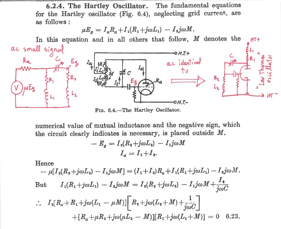
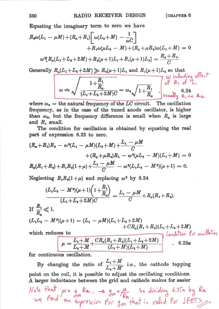
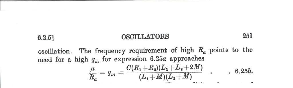
"My intention is to apply the same small signal technique to the Thermen oscillator with the antenna series tank attached. Hopefully I'll get a formula for w=w(C-hand) in oscillation."

I didnt think it was possible to do this with the kind of "simple" calculations you are using above - (but dont take my word on this, I am a maths luddite - Honestly, I have not checked your calculations.. All I have checked is that there is nothing in them which seems utterly incomprehensible..;-) .. My understanding (and expierience attempting to calculate / simulate antenna LC interacting with tank LC) is that you need much more complexity - A pure mathematical formula for this is way beyond me - I tried useing successive aproximation, and now I use Dewsters spreadsheet which runs VB...

Lately, although its laborious, I have taken the capacitance results (antenna / hand) from a modified version of Dewsters spreadsheet (returning capacitance values for 5cm distance increments), and fed these results into my Proteus simulation.. then run a full circuit simulation using these values - These simulation "experiments" on the Lev oscillator looked good... But the physical reality was far less good.

One other thing.. I tried simulating a couple of your oscillators using Proteus (LISA/PROSPICE - an extended 3F5 engine) and got some strange results - can you advise of some parameters / values.. in particular, the inductors series resistance or anything else related to the inductors... I am getting much higher voltages than I expect to see.. and also convergence issues I dont expect.. I want to run the simulations in LT Spice next, but starting with what you have would be useful.

Fred.

Posted: 4/23/2013 8:44:48 AM
Juan

From: Valencia, Spain

Joined: 4/21/2013

Fred

I agree that the final analytical formulas are only of relative interest for studyng the real linearization of the front end response. At the end, the capacitor-hand-floor relation is modeled by a simple capacitor between the antenna and ground, but the model itself for this capacitance is quite objectionable.  In "Physics of the Theremin" by Skeldon, Reid et al, there is a proposal to model this hand capacitance, but it does not seems too promising.

Also these analytical formulas are only a first approach  Simulation with more complicated models should be more accurate. The real utility is just to know the big influences of each parameter  For instance, from my results it is quite clear that L1 and L2 can be different in a Thermen oscillator (as it is usual in a Hartley oscillator), as far as the relation  between mu, L1, L2 and M is fulfilled. In fact being L1 and L2 equal (if tightly coupled), the feed back is so big that only a minimal amplification is required.

I have already derived a long w=w(C-hand) formula for oscillator with series coil in antenna, but I am trying to simplify the result, or to make it more presentable, in order to learn what is inside. I have my doubts that it is of real utility for linearization study, but who knows. In any case it is interesting.

As you know a Theremin is the worst thing you can think for an analogue design, it has all you can imagine to make things difficult (small capacitance interactions, critical parameters depending on temperatures, non-linearities to characterizy the sound, and more). So any simulation or analytical formula will be only a very rough approximation. A digital design simulates OK and usually the prototype works as expected, an analogue design simulates so and so and sometimes the prototype works, but for sure a Theremin prototype will never work as expected. 

Juan


Posted: 4/23/2013 9:14:26 AM
Juan

From: Valencia, Spain

Joined: 4/21/2013

Fred

On the simulations all parts are ideal, L1 and L2 have no internal resistances.

I have run a "trasient simulation" of 2 ms, with a very small time step. Perhaps the model for the JFET is causing problems. I think the bias point at starting for Thermen-A and B is creating a big current peak until is stabilizes creating a negative bias on the gate. Perhaps this is causing convergence problems. Sometimes, I skip the initial bias calculation if the initial bias is strange, and it converges.

Another question. In all the schematics for Theremin oscillators active devices are usually single parts, bjt, JFets, or tubes (I mean for sinusoidal output Theremins, not for "digital" clock oscillators). The main problem for a Theremin oscillator is frequency drift. One of the main causes of frequency drift is  temperature change of parameters in the active device. And obvious solution would be to use an opamp with an fixed amplification factor stabilized by feed-back resistors. Resistors also can change with temperature, but much less than a semiconductor. There are lots of opamps with bandwidth of several MHz, not expensive ones. Why opamps are not more used for Theremin oscillators? It seems the ideal active device. There is a thread on this subject?

Juan

Posted: 4/24/2013 8:30:16 AM
FredM

From: Eastleigh, Hampshire, U.K. ................................... Fred Mundell. ................................... Electronics Engineer. (Primarily Analogue) .. CV Synths 1974-1980 .. Theremin developer 2007 to present .. soon to be Developing / Trading as WaveCrafter.com . ...................................

Joined: 12/7/2007

" There are lots of opamps with bandwidth of several MHz, not expensive ones. Why opamps are not more used for Theremin oscillators? It seems the ideal active device. There is a thread on this subject?" - Juan

I have never seen any thread or discussion on using opamps in this way, and yes, there are some lowish cost opamps which are well suited - the LM6142 for example is one I have used, having RR I/O and the ability to drive high capacitance loads - But there are many more at lower cost when RR I/O is not required.

As regards thermal issues, It seems to me that it is the inductors which are the main cause of problems - particularly if one uses ferrites.. The ferrite even in something like a IFT contributes more drift in my expierience than all the other thermal variables combined.

I am inclined to thinking that the easiest solution is a crude one - Have a few resistors on the board deliberately running as "heaters", having a thermal sensor monitoring the board temperature, and controlling these "heaters", and enclosing the board in a thermally insulating assembly - a few minutes after power-up, the board reaches the defined temperature (say 50C) and provided all the combined normal dissipations are insufficient to continue raising the temperature, one has an assembly sitting at a constant temperature and can use almost any components one wants.

In fact, I have found that even without active heating, mounting a board between two layers of polyurithane foam hugely improves performance - there will still be drift, but this is far slower than for a board directly subject to direct influence by changing ambient temperature.

Fred.

Posted: 4/29/2013 9:15:29 AM
Juan

From: Valencia, Spain

Joined: 4/21/2013

Still I am trying to find a usable expression for Thermen oscillator with antenna series coil. In the meantime, I have been looking some of the tube books in my physical and virtual library and I have found a development for a shunt fed Hartley oscillator that is of exact application to Thermen oscillator. The good thing is that the development includes non ideal coils, that is internal resistance (I used ideal coils in my deduction).

The reference is from "Radio Receiver Design" by K.R. Sturley -1943. This is a triode circuit but the result can be applied to JFET easily (using gm, instead of mu). This book, and a bunch of other log-ago out of print tube books, can be (legally) downloaded from http://www.tubebooks.org/technical_books_online.htm

So here are the results:


That is, in a couple of pages a development for Hartley oscillator I have never found in modern textbooks (in the Sturley book there are similar developments for tuned-plate, tuned-grid/Armstrong, and Colpitts oscillators). Given the level of the books they used, I think that engineers from the past were much more clever than current ones.

Note that if R1=R2=0 (ideal coils) the expressions are the ones I found. But Mr Sturley has done a nice job including coil resistances.

Really there are a lot of useful ideas in these old books from pre-pspice radio days.


Posted: 4/29/2013 10:14:19 AM
Juan

From: Valencia, Spain

Joined: 4/21/2013

Fred

I think that your idea for thermal control was used by some analog synthesizer manufacturer (early 70') to keep the audio VCOs more or less in tune. Certainly it was not Moog (original modular synth VCOs were famous for tone drifting, even minimoog was not easy to keep in tune). I think the company was E-Mu, quite famous for ultra-stable VCOs. The trick was to heat the transistors in the oscillator to a high stable temperature. But these VCOs were RC oscillators, so the main cause of drift were probably the semiconductors.

Ferrite characteristics are quite temperature dependent. Perhaps this is a good reason to use big air core inductors. But then you have to use capacitors trimmers but modern trimers are not NC0 capacitors. The alternate and easy solution are varactors (or even reversed normal diodes). But then we have again a temperature dependent semiconductor in the core of the LC network. Your "brute force" approach seems a good solution for all problems.

Juan


Posted: 4/29/2013 2:58:56 PM
Juan

From: Valencia, Spain

Joined: 4/21/2013

When playing with simulations of the different kind of LC oscillators it is nice to observe that the signal voltage can be much higher than the input voltage, as the coil can store a lot of energy. The problem is then that some of the safe voltage parameters of the humble JFET or bipolar are easily exceeded, so many of the simulations cannot be converted into real circuit, except that the input voltage is very low to keep the peak to peak voltage of the output signal within reasonable limits. Big oscillations signals are nice, because then a lot of interferences can be avoided. In these days of low-energy light (each bulb includes a wild switching power supply irradiating 20-60KHz and noisy harmonics) I think it is a very good idea to have a very large signal in the oscillators (or in the antennas, in fact).

One option is to use tubes, which employ high voltages anyway and are quite immune to even higher pulsating voltages, exceeding the published ratings. Another option is to decouple the oscillator tank from the semiconductors, so the oscillator tank can go, say up to 80Vpp, while the voltages in the circuit are in the normal ranges (10Vpp or so). The tank is really a voltage transformer: for the side of the antenna we have high voltages and the capacitor setting the frequency, for the side of the circuit a lower inductance coil converting low voltages, with a tight inductive coupling between both sides. This is sometimes referred as a Meissner oscillator (sometimes confused with Armstrong, but not really the same)  or a Reinhartz oscillator .

So with this transformer idea we can have low voltages in the circuit and high voltages in the tank and antenna. Then we could use a fully differential oscillator. Etherwave oscillator is sometime referred as a differential oscillator, but as the tank is at one collector and the other collector is connected to V+, then really it is not using advantage of the differential topology, it is really very unbalanced. I think it should be nice to have a fully differential oscillator, so we could extract a fully balanced oscillation signal between collectors (or sources) or, alternatively, a normal non balanced signal from one of the collectors (or sources) to ground. Most of the integrated LC oscillators we have in our mobile phones are of fully differential CMOS technology in nice topologies generating some GHz. Then combining a differential oscillator with a transformer we can have the LC tank in one side and a center tapped L tank in the other, connected to the differential oscillator (in a similar to the audio transformer in a tube power amplifier, but with a capacitor instead of a loudspeaker). The coupling between tank and circuit is only inductive. The tank is “single ended”, the circuit is fully balanced.

Which use we could have for a fully balanced signal? We could use a fully balanced multiplier as mixer. I am thinking for instance on AD633 (a four quadrant multiplier available in DIP8, around 9€, expensive but not terrible). With this circuit we have real analog multiplication, then real heterodyning resulting in f1+f2 and f1-f2. A simple low pass filter and the audio will be there. Of course a mixer based on AD633 will not distort as a tetrode tube, but in any case this is just an idea to make things different.

Other advantage of a fully differential oscillator is the rejection of common mode supply signal. Probably this will make oscillators a little more immune to synchronization through power supply. Also balanced collector to collector signal is double the amplitude of collector to ground.

I will try to post some circuit proposals and simulations on above ideas.

Juan

Posted: 4/29/2013 3:53:01 PM
FredM

From: Eastleigh, Hampshire, U.K. ................................... Fred Mundell. ................................... Electronics Engineer. (Primarily Analogue) .. CV Synths 1974-1980 .. Theremin developer 2007 to present .. soon to be Developing / Trading as WaveCrafter.com . ...................................

Joined: 12/7/2007

Thank you for that awesome link, Juan !

Really nostalgic looking over those titles! - Many of those books were my college text books, and trying to grapple with them to pass my exams utterly destroyed any possible social life, and eliminated any chance I had of becoming a normal social human being! LOL ;-)

(I had left school at 14 for health reasons, and was studying that stuff instead - took my finals at 16.. Sad how things I learned for exams are the things I remember least! ... But  a few minutes of looking at those books it all comes back, only I now can see what eluded or confused me back then.. )

"I think that your idea for thermal control was used by some analog synthesizer manufacturer (early 70') to keep the audio VCOs more or less in tune." - Juan

Oh yes - Lots of synth developers used "ovening" .. One (IMO) of the nicest Moog Synths (in terms of stability - NOT the user interface!) was the Source.. This whole synth was heated and thermostatically controlled.. Then use of heated transistor arrays (one transistor used as a heater, one as a temperature sensor, and the remaining used for exponential conversion) was popular (was employed on the PE-Minisonic published in 1974) - Its certainly not "my idea" - The first time I came across the idea was probably from the PE Minisonic article - I had built several synths by the time the article appeared, and was building a polyphonic which had a HF VCO with TOS and TDA1008 deviders and EG's.. The Minisonic ovening idea was incorporated virtually unchanged into this instrument, and solved the pitch drift.

Alas, the simplicity of a array on common substrate doesnt really help theremin stability.. and "ovening" all the components which can affect temperature means "ovening" the whole front-end.

Fred.

Posted: 4/29/2013 7:06:49 PM
dewster

From: Northern NJ, USA

Joined: 2/17/2012

"When playing with simulations of the different kind of LC oscillators it is nice to observe that the signal voltage can be much higher than the input voltage, as the coil can store a lot of energy. The problem is then that some of the safe voltage parameters of the humble JFET or bipolar are easily exceeded, so many of the simulations cannot be converted into real circuit, except that the input voltage is very low to keep the peak to peak voltage of the output signal within reasonable limits. Big oscillations signals are nice, because then a lot of interferences can be avoided. In these days of low-energy light (each bulb includes a wild switching power supply irradiating 20-60KHz and noisy harmonics) I think it is a very good idea to have a very large signal in the oscillators (or in the antennas, in fact)."  - Juan

Yes, high antenna voltages can definitely increase SNR, but they must be generated and dealt with.  The series inductor going to the antenna (AKA "EQ" or "linearizing" inductor) can often boost the voltage quite a bit.

Another quite simple oscillator option is to use a series LC tank with the C end grounded, drive the L end with a low impedance / low voltage signal, connect the EQ coil and antenna at the LC intersection.  With large L and small C you can get hundreds of volts output swing at the antenna with only a volt or so in.  Drive can be a square wave and you will still get a nice sine wave at the antenna due to the low pass filtering of the LC.  Make the tank C a capacitive voltage divider (two C's in series, the smaller on the L side, the larger to ground) and you get a low impedance and low voltage 90 degree feedback for the oscillator.  Buffer and delay this with an RC to get 180 degree feedback, invert to get 360 degrees, then close the loop for oscillation.

I haven't tried my "capless" oscillator topology yet - it employs an air core transformer to resonate with the antenna capacitance - no physical tank capacitance!  This should theoretically give maximum sensitivity (for an LC oscillator).  No voltage divider is necessary because the primary side never exceeds the supply voltage, and feedback is 180 degrees so no additional RC is necessary.  Low voltage square wave input is fine here also, and the EQ coil can be wound on the same core former as the transformer.  (That is, if it actually works like the simulation!)

Posted: 4/29/2013 9:17:00 PM
FredM

From: Eastleigh, Hampshire, U.K. ................................... Fred Mundell. ................................... Electronics Engineer. (Primarily Analogue) .. CV Synths 1974-1980 .. Theremin developer 2007 to present .. soon to be Developing / Trading as WaveCrafter.com . ...................................

Joined: 12/7/2007

"That is, if it actually works like the simulation!" - Dewster

If your circuit is anything like what I think it is, it does work - Damn well! - I havent used air coil transformer - just a simple IFT with antenna having a passive ground shield (total about 25pF) and running at about 1.2Mhz (close to resonance).. Driving the large adjustable (400uH to about 900uH) coil with a 5V square wave from a MOSFET driver IC, and picking the signal up from the isolated small secondary winding (about 30uH).

Fred.

You must be logged in to post a reply. Please log in or register for a new account.