New Mixer Topology

Posted: 2/27/2013 6:39:11 PM
FredM

From: Eastleigh, Hampshire, U.K. ................................... Fred Mundell. ................................... Electronics Engineer. (Primarily Analogue) .. CV Synths 1974-1980 .. Theremin developer 2007 to present .. soon to be Developing / Trading as WaveCrafter.com . ...................................

Joined: 12/7/2007

WITH REFERENCE TO FOLLOWING REPLIES - THE WORD "NEW" IS A BAD CHOICE - RARELY (if ever) IS ANYTHING ABSOLUTELY "NEW".

SO PLEASE REGARD THE "NEW" AS A STATEMENT THAT I HAVE NEVER SEEN ANY SCHEME LIKE I PRESENT HERE PUBLISHED - I HAVE NEVER SEEN THIS SCHEME APPLIED TO ANY THEREMIN.

"NEW" or "NOT NEW" - I think this is the first time this scheme for THEREMINS has ever been PUBLISHED OR DISCLOSED.

BUT - IF I AM WRONG, IF ANYONE KNOWS OF A PRIOR PUBLICATION OF THIS THEREMIN IDEA, PLEASE LET ME KNOW!

IN SUCH A CASE I WILL ACKNOWLEDGE SUCH AN INDIVIDUAL AND CREDIT THEM WITH THIS IDEA!


The first posting on this subject started HERE but I moved it to this thread, as once again I was hijacking Dewsters thread!  Sorry Dewster ;-)

(this first section is probably mostly waffle.. the real "meat" is down at the bottom..)

I have been exploring mixer topologies extensively recently - The Lev "clone" project led to this.. I even dug up some tubes and transformers and messed with them to try see what was happenning in the Lev mixer - Alas, I still cannot see a clear mechanism by which the frequency dependent behaviour occurs, so reverted to "top down" - as in, I know what I want - I dont know how Lev got it, so I must devise a way to get the same result even if through some other mechanism.... I achieved this before - But the circuit was way too complex - so exploring "new" ideas seemed the best route.

In fact, the irony is that the more "perfect" the mixer (as in, the closer to a true multiplier) the less useful it is musically - The waveforms from the oscillators do not carry enough interesting stuff, and even the harmonics present are attenuated in a true mixing process.

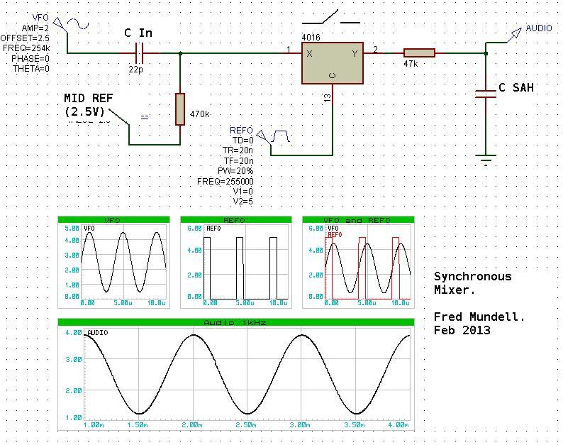
And this is where synchronous demodulation really scores - one turns the reference oscillator into a square wave, and shapes this to a triangle wave.. This triangle wave then drives a comparator, the other input going to a voltage that determines the output pulse width.. This output gates a CMOS switch, this CMOS switch has the variable oscillator as its input, and the other side is connected to a capacitor via a resistor (a sort of combined integrator / SAH).

If the PW is set quite short, one gets an audio difference waveform on the capacitor which is representitive of the waveform from the variable oscillator (I think any harmonics on this waveform are attenuated at 3db/octave) - One does not need harmonics on both the reference and variable signals - whats on the variable oscillator waveform comes out in the audio.

The above means that one can shape the variable oscillator waveform alone, and get this to influence the sound.. One can also get some wonderful waveforms by squaring the variable oscillator signal and doing the same PWM mechanism as applied to the reference oscillator - by varying the pulse widths of both one can produce triangle, square, pulse waveforms etc... Having two "channels", mixing raw analogue VFO waveforms with "processed" VFO waveforms, almost every possible waveform is achievable - and one does not lose the analogue changes (such as waveshape changes which occur as oscillators start to synchronise at the bass end) unless one wants to.. This is the big advantage - the main problem with mixed signal heterodyning of my past designs has been the loss of the analogue shape content, and the requirement to synthesise this - this new design gives, I think, the best of both worlds.

Because the above is all based on voltage control which determines the pulse widths, frequency dependent harmonics are easy to produce (simply drive this from a voltage derived from the VFO frequency).. The whole circuit uses one dual comparator, one HC4066 quad CMOS switch, a few R's and C's...

All the above is running in simulation, and I can play the sounds it produces - Its a long way from Lev's mixers topology, but I believe it can reproduce all the 'core' waveforms from his instruments (and many more, including quite pure sine waves if one wants that)... Need to add a few gyrators in the audio path to mimic the audio transformer charactaristics, and I think I could be there! ;-)

Fred.


Here is the most basic form: The narrower the sampling pulses, the lower the HF content on the audio signal - In reality I use a double track + hold sampling system which eliminates all HF (as in RF components - there are no "sum" components with this method, only the sampling frequency appears on the audio - and this is eliminated by double track+hold) on the audio regardless of pulse width.

Values given are probably not meaningfull - just patched together to show principle of operation.


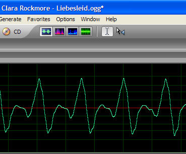
This shows a more complex waveform from the VFO, and how this is reproduced at the audio difference frequency.. The circuit that produced this is slightly more complex than the circuit shown above - but not by much.. the circuit shown above will produce an almost identical copy, but has a few db's attenuation of the higher harmonics. The full circuit entirely eliminates the "fur" on the audio waveform, and gives almost perfect replication of the VFO waveform.

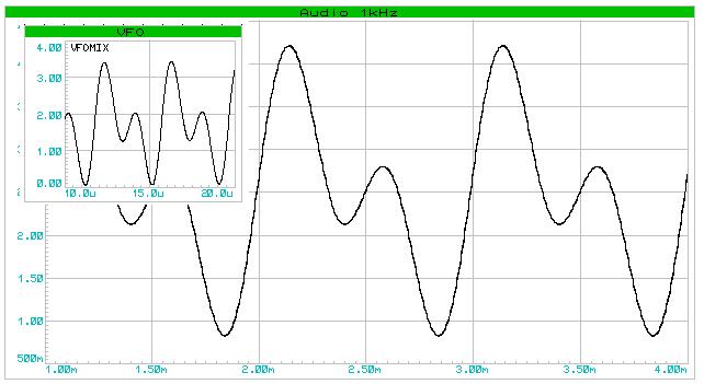
 Note also that the above was "fiddled" by having the reference frequency 1kHz below the VFO frequency.. Normal operation (REF > VFO) the waveform is the other way round.. as in, the audio will be transposed horizontally.. this makes absolutely no difference to the sound, its just a phase relationship.

One can actually "square" either the VFO or REF, to use as a "gating" signal..

This whole scheme is a sort of "real time sampling" system perhaps more than a synchronous demodulation as I said before - there is actually no "mixing" or "modulation" occurring at all - In fact, Im not even sure that "heterodyning" applies - I think it does, but perhaps not in any conventional way - the "beat" is almost a deliberate "aliasing" perhaps...


THIS IDEA AND THE SCHEMATICS ETC RELATED TO IT ARE UNSUITABLE FOR ANYONE WHO DOES NOT UNDERSTAND SAMPLE AND HOLD CIRCUITS, AND FOR ANYONE NOT  ABOVE BASIC ELECTRONIC HOBBYIST LEVEL.. YOU CANNOT EXPECT TO JUST BUILD THESE CIRCUITS AND HAVE THEM WORK WITHOUT UNDERSTANDING THEM AND DOING THE REQUIRED ADAPTATIONS TO FIT THE APPLICATION! << This warning was added on 3/29/2013 1:18:28 AM >>


Posted: 2/27/2013 7:01:11 PM
dewster

From: Northern NJ, USA

Joined: 2/17/2012

I noticed the beginning of "Liebesleid" on Clara's "Lost" CD starts with just her Theremin playing.  Mix L & R to mono in Adobe Audition and one gets a waveform very similar ("transposed horizontally") to your simulation above:

Posted: 2/27/2013 7:27:04 PM
FredM

From: Eastleigh, Hampshire, U.K. ................................... Fred Mundell. ................................... Electronics Engineer. (Primarily Analogue) .. CV Synths 1974-1980 .. Theremin developer 2007 to present .. soon to be Developing / Trading as WaveCrafter.com . ...................................

Joined: 12/7/2007

"I noticed the beginning of "Liebesleid" on Clara's "Lost" CD starts with just her Theremin playing.  Mix L & R to mono in Adobe Audition and one gets a waveform very similar ("transposed horizontally") to your simulation above" - Dewster

Oh yes ;-) Just change the phase of the 2nd harmonic and one gets a close match - my simulation only mixed fundamental and 2nd harmonic (in fact, the waveforms would look a lot more alike if I had left the REF > VFO frequency) - add a few more harmonics and one gets the Claramin waveform (almost ;-).

Sadly though, its not quite as simple as that.. but this new mixer (more than) halves the complexity required to implement a fully additive analogue "engine" capable of creating any waveform.. I was bugged by having to duplicate all the harmonic mixtures on both the reference and variable oscillators, in order to produce audio through heterodyning which recovered these.. (particularly as I needed the VFO harmonics to track the varying frequency) (IMO, creating "any" waveform is not enough - The most important thing is the way the waveform changes as the pitch (and possibly volume) changes - It is this which gives life to a musical sound IMO, and I believe that this is where Lev's theremins are most superior.)

Now, all I need is to produce one set of harmonics at fixed frequencies, mix these to taste, vary each harmonic dynamically as a function of frequency / (volume) to taste, and square up the VFO as the "sample" pulses..

For me, this is huge! - It brings my ultimate theremin within reach - and also, with my voltage control of theremin pitch, allows for the creation of additive VCO's.

Fred.


Posted: 2/27/2013 10:50:58 PM
Thierry

From: Colmar, France

Joined: 12/31/2007

Just my two cents: Fred, you write that you fear that neither mixing nor modulating would take place in your "system". That is wrong in my eyes because every sampling is modulating at the same time. Ask Mr Nyquist! :-)

The idea of using a kind of switching demodulator in a theremin is not new. Anthony Henk did it already in 1994: the signal from the ref osc is fed (2.5Vpp DC free) into the drain of a 2N3819 FET which acts as a variable resistor/switch (no DC between drain and source, both on ground level). The variable osc's signal is clamped through a capacitor with a diode to be between -3V and +0.7V and fed into the gate. The FET's source goes to 2 RC low passes in series before another FET will amplify the resulting audio signal in a ordinary common source circuit. I think that in this configuration the source and drain pins of the switching FET could even be reversed without any impact on the principle of operation...

The more I get insight into different theremin circuits, the more I feel that it will be difficult to create something really new. The best ideas seem already to have been explored. That's why the first derivative of my motivation curve is actually rather negative.

Posted: 2/28/2013 2:02:11 PM
FredM

From: Eastleigh, Hampshire, U.K. ................................... Fred Mundell. ................................... Electronics Engineer. (Primarily Analogue) .. CV Synths 1974-1980 .. Theremin developer 2007 to present .. soon to be Developing / Trading as WaveCrafter.com . ...................................

Joined: 12/7/2007

Thanks for your input, Thierry - I really value your perspective, particularly with regard to mathematical insights where I am a minion.. ;-)

"The more I get insight into different theremin circuits, the more I feel that it will be difficult to create something really new. The best ideas seem already to have been explored. That's why the first derivative of my motivation curve is actually rather negative." - Thierry

LOL ;-) .. If its true "newness" one is after, something which nobody has ever done, in any way, before - well, the "motivation curve" will almost always be on the -ve side of zero! - not just for theremins, but for everything!

The only way, IMO, to move into the +ve of the "motivation curve" is to accept that everything one thinks of is likely to have been thought of before - but still get satisfaction at having thought of it.. There is (for me) a huge difference between reading someone elses ideas, and "copying" them or applying them, and devising the scheme myself and applying my ideas. From a commercial / financial perspective, an idea is "valuable" if you can claim it as your original and get "ownership" of it through patents or whatever - But I am old and cynical enough to know that, in reality, even if you have an "original" idea the chance of this being "stolen" is orders of magnitude greater than the chance of making real money from it.

"Fred, you write that you fear that neither mixing nor modulating would take place in your "system". That is wrong in my eyes because every sampling is modulating at the same time. Ask Mr Nyquist! :-)"

Sorry, this was not what I meant to say, and was a bit "sloppy" - There is no "mixing" or "modulation" (that I can see = TICS) in the "normal" way that occurs when combining two signals through simple arithmetic functions.. There is no modulated  signal (TICS) to demodulate, hence I do not think "demodulation" is the best term to describe what is happenning.. With heterodyning, the result is a mathematical product which gives the sum and difference of all input frequencies, on removing the sum components, one has the difference components - In order to control the harmonic content of the difference, one must modify the harmonic content of both input frequencies - changing one inputs harmonic content will not alter the harmonic content of the difference signal if the harmonics are not present on the other input..

With this "RT sampling" scheme, the sampled signal appears shifted to the difference frequency - one only needs to change the harmonic content (shape) of the sampled signal to produce the same shape on the difference (down shifted) signal.. Nyquist applies, obviously, and this can be demonstrated easily by changing the sampling pulse width - the wider the sampling, the lower the resolution and the higher the unwanted HF content from the sampling frequency is on the output signal... My full scheme (circuit not shown) uses only the rising and/or falling edges for sampling (there are in fact two seperate track and hold circuits, which are swapped alternately), so the effective sampling "pulse" is tiny (<50ns) .. One ends up with a stepped audio waveform, steps occurring at the sampling frequency - these steps are tiny and integrated away long before one gets to any audio processing..

The relationship between the sampling frequency and the sampled frequency is quite different to that found in normal sampling systems - one is not sampling a slowly changing signal with a fast sampling frequency - one is sampling in a condition where both the sampling frequency and the sampled frequency are almost identical - All the normal ways of thinking about sampling are turned on their head.. The aliasing IS (I think - but am not sure..) what one is using as the output!

So yes - I think Nyquist theory still applies - but possibly not in the way you are inferring.. I see no possibility of generating any unwanted artifacts from this particular form of sampling - the usual sampling problem is aliasing, where the frequency of what is being sampled is too high, and results in sampling "errors" .. But I THINK* that what I am doing is actually "deliberately" generating this kind of "error" and the "error" is the downshifted audio I want!

"The idea of using a kind of switching demodulator in a theremin is not new. Anthony Henk did it already in 1994: the signal from the ref osc is fed (2.5Vpp DC free) into the drain of a 2N3819 FET which acts as a variable resistor/switch (no DC between drain and source, both on ground level). The variable osc's signal is clamped through a capacitor with a diode to be between -3V and +0.7V and fed into the gate. The FET's source goes to 2 RC low passes in series before another FET will amplify the resulting audio signal in a ordinary common source circuit. I think that in this configuration the source and drain pins of the switching FET could even be reversed without any impact on the principle of operation..."

It sound like Anthony Henk was using a scheme at least similar if not identical - but that the true power of the scheme was perhaps not recognised by him.. That he was using the scheme as a demodulator.. I could easily have made the same "mistake" - At first I was looking at the scheme in terms of "demodulation / mixing" and messing with the input signals / pulse widths etc to achieve waveshaping.. It was great for this.. But when I saw it as a "sampling system" and changed the design to optimise this function, a whole huge new world opened up... The simple scheme you describe Anthony Henk using is similar to the scheme of my circuit - its sampling possibilities are limited by practical factors such as the minimum pulse width that is usable.... this width defines the resolution possible.

Fred.

 *ps.. for me, it actually doesnt matter what this idea "is" in terms of whether its a "synchronous demodulator" or a "heterodyning mixer" or a "real time sampling system" or an "alias generator" LOL ;-) .. All that matters is that it does what I need it to do!

I would, nonetheless, be really interested in knowing the correct technical / mathematical "analysis" of this scheme, to know what it "should" be called, and how it relates, academically, to Nyquist.

Posted: 2/28/2013 3:46:48 PM
ILYA

From: Theremin Motherland

Joined: 11/13/2005

Thierry: is not new

Moreover, the same method (stroboscopic sampling) is widely used in DSOs to transfer GHz waveforms under Nyquist frequencies.

Seems, Fred, that you steps on my heels, because this summer I have tried the synchronous demodulation in hardware, with a full satisfaction on Theory and Practice coincidence.

Thierry: I feel that it will be difficult to create something really new

The next idea after s.d. was to reconcile a digital guy with analog girl: to make the heterodyning by ADC! The close  frequencies of signal from VPO and ADC sampling rate gives the same result. The postprocessing (filtering, reverberation, etc.) can be made by DSP or uC. Most processors have an internal ADC with a pin for external clocking , so the problem of correlated thermal drift may be easily solved.

Thierry, what do you know about such theremin types?

Posted: 2/28/2013 4:37:42 PM
FredM

From: Eastleigh, Hampshire, U.K. ................................... Fred Mundell. ................................... Electronics Engineer. (Primarily Analogue) .. CV Synths 1974-1980 .. Theremin developer 2007 to present .. soon to be Developing / Trading as WaveCrafter.com . ...................................

Joined: 12/7/2007

"Seems, Fred, that you steps on my heels, because this summer I have tried the synchronous demodulation in hardware, with a full satisfaction on Theory and Practice coincidence." - Ilya

Great! - not sure about "stepping on heels" LOL ;-) - Also, you say you tried "synchronous demodulation" - I do not believe that this is what I am doing! "stroboscopic sampling" may well be what I am doing.

All this "secret" theremin research going on - All these "undisclosed" insights into unpublished theremin designs..

Am I the only one "foolish" enough to share what I come across ? Does everyone else guard their discoveries and "insights" ?  .. No .. Im not..... Dewster publishes his stuff and gives his excellent insights and tools freely - but he is one of the rare exceptions.

In the main, theremin developers seem to have little interest advancing the art - they are happy to jump in with critisism and "its not new - I did that before you did!"

I really dont care.

I have never seen anyone publish anything for theremins like I have published here - So how many others have done this is in their private labs is, to me, completely irrelevant. If someone else has published the idea prior to me, let me know - I will then acknowledge them as the person who should get "credit" for it.

If you have a good idea regarding theremin technology, share it - or at least dont try to lay any "claim" to it when someone else shares it.

Thats my opinion anyway - I have been on the "other side" of this quite often, when someone publishes (via patent or whatever) something I had thought of and been developing.. Yeah, its a bummer - but thats life! LOL ;-)

I also have a number of theremin ideas and developments I have not disclosed (I only disclose when I am reasonably sure I have enough useful stuff to share and that I am not going to waste anyones time on drivel - I never actually intended to publish this idea until I had worked through the theoretical aspects more comprehensively, and published the first post more on impulse than "deliberately")  - and there is always the possibility that someone else is working on the same ideas and may publish / disclose before I do..

I do hope I have the dignity in such an event, that I will not say or do anything to "undermine" that person, even if I am bitterly dissapointed at not having been the first to publish.

Fred.

Posted: 2/28/2013 6:27:44 PM
dewster

From: Northern NJ, USA

Joined: 2/17/2012

If anything, the mystery shrouding a somewhat different seeming product piques curiosity about how it works, so anything unusual will just get reverse engineered that much faster. 

The only thing I'm slightly concerned about is some company like Bheringer taking one of my designs whole and making it for $100 retail or something.  But I have a feeling the Theremin market is too small for them to really care about it, which is one of its beauties, actually.

Posted: 2/28/2013 7:00:18 PM
ILYA

From: Theremin Motherland

Joined: 11/13/2005

Fred, above I have already shared one of my ideas (heterodyning by ADC, unfortunately yet not implemented) is that enough? All I do is just hobby. And I dont't write like this "I will probably delete this posting". 

At all, IMO, the mixer is one of the problem-less parts in theremin.

Posted: 2/28/2013 9:17:47 PM
FredM

From: Eastleigh, Hampshire, U.K. ................................... Fred Mundell. ................................... Electronics Engineer. (Primarily Analogue) .. CV Synths 1974-1980 .. Theremin developer 2007 to present .. soon to be Developing / Trading as WaveCrafter.com . ...................................

Joined: 12/7/2007

RE: REPLY TO ILYA AND RS:

"As far as getting a nice theremin sound I agree as single diode detection works for me. " - RS

"At all, IMO, the mixer is one of the problem-less parts in theremin." - Ilya

I am not talking about "problem less" - There is no "problem" extracting the difference frequency from a mixed signal - there are dozens of ways to do this, they all work, and many are extremely simple.

BUT

Replace the mixer tube in one of Lev's theremins with a diode mixer from an EW and you will lose EVERYTHING worthwhile from the sound of Levs theremin IMO - so trying to say that a diode mixer is all you need is kinda missing the point! - sure - its all you "need" .. All you need to make a guitar is some crude guitar shaped structure and some rusty strings.. As long as you can pull these strings to the right tension and they twang at the right pitch and the frets are in the right places, you have a guitar..

The mixer is, IMO, THE most important part, by an extremely long way, in what determines the sound produced by a theremin.

Sure, you can take any bog-standard demodulator and then distort the resulting audio with post processing to make it look like whatever you want, and ALMOST sound like whatever you want..

But I am tired of this pointless nonsense - I presented a technical idea offering the ability to take any waveshape on a single HF oscillator, and down-shift this to the difference (audio) frequency.

Even if waveform replication was not wanted, this scheme is one of the simplest, cheapest and cleanest methods of obtaining an audio difference frequency that I have seen ..

If you want to use a diode, use a diode - If you want to get rid of the HF rubbish which bugs your life, without needing fancy filters, "my" idea will do this even if thats all you use it for.

""the mixer is one of the problem-less parts in theremin" - Ilya

If you are looking for "problem-less" why on earth are you looking at using an ADC ? The reason must be something other than "problems", LOL ;-)

"Fred, above I have already shared one of my ideas (heterodyning by ADC, unfortunately yet not implemented)"

No - You havent shared anything! your "to make the heterodyning by ADC! The close  frequencies of signal from VPO and ADC sampling rate gives the same result. The postprocessing (filtering, reverberation, etc.) can be made by DSP or uC. Most processors have an internal ADC with a pin for external clocking , so the problem of correlated thermal drift may be easily solved.

- Is like me saying "I have a design which uses a heterodyning ALU,The close  frequencies of signal from VPO and ALU clocking rate gives the same result. The postprocessing (filtering, reverberation, etc.) can be made by DSP or uC. All processors have an internal ALU with a pin for external clocking , so the problem of correlated thermal drift may be easily solved "

- No information is conveyed, no schematics or data of any useful kind is presented - there is NOTHING which can be used or even seriously thought about!.. I may go off and think about using an ADC as a heterodyning mixer (although this is unlikely - I can think of better ways to waste my time than try to mind-read or deduce an idea given a few almost meaningless words without any contaxtual framework or description or anything to put flesh on the single bone), but if I did there is no certainty that I would come up with the same idea you had!

You, on the other hand, could take the information I have presented here and actually build the circuit I presented and get it running in less than  a day, even if you were slow! ... You could certainly simulate the idea using nothing more than I have given, in a couple of hours MAX using LT-Spice.

-------------------------------------------------------------------------------------------

Anyone wanting to seriously discuss matters in the context of this forum, which is TECHNICAL THEORY, please do so - anyone wanting to discuss their hobby ideas, well - the constructors forum is probably better suited to this.

Me ? - Im not going to bother posting ideas here anymore .. Anyone who wants to subscribe to my email newsletter and get a link and code for a private forum I will be setting up, please email me - Please give all details about youself, including your TW name, so I can exclude time wasters.

Fred.

You must be logged in to post a reply. Please log in or register for a new account.