Battery Supply for EW ? (condensed and meaningful posts)

Posted: 4/16/2013 7:26:47 AM
FredM

From: Eastleigh, Hampshire, U.K. ................................... Fred Mundell. ................................... Electronics Engineer. (Primarily Analogue) .. CV Synths 1974-1980 .. Theremin developer 2007 to present .. soon to be Developing / Trading as WaveCrafter.com . ...................................

Joined: 12/7/2007

>> Skip this if you arent confused ;-)

This threads title and history:

I moved my content here from a thread which went "wrong" and was later removed by the moderators..  The original thread was "Battery Supply for EW ?" and I created a new thread  "Battery Supply for EW ? <filtered>" (this thread)  into which I moved my postings, leaving the old thread which (IMO) contained a couple (2) of relevant / valuable postings from others (I can only move my posts - only moderators can move others).. 

The original thread was deleted by the moderators, and this thread re-named to its present "Battery Supply for EW ? (condensed and meaningful posts)" by the moderators. I just wish to make this clear, so that nobody thinks I am declaring my posts to be "meaningful".  ;->

<<

Here is where the not so "Meaningful"  "introduction" stuff starts ;-)  à

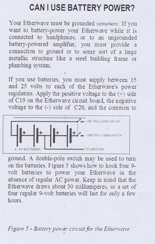
I have over the last few years had several enquiries about adapting the EW for use with batteries .. this is probably due to a thread I posted on (or started?) back in 2008..

I keep asking those who email me about this, to open a thread here on TW so that those with more hands-on expierience of the EW can get involved.. But this never happens.

So, I am pasting bits from some of these emails, and some from my replies / suggestions, here - and forcing the matter.. I dont want to continue one-to-one "support" on a matter about which I know little ..

Any ideas / suggestions I present are completely untested.. They are presented for purposes of possible discussion only.

"I am a member of thereminworld.com and was reading an old post of your from 2008 about
connecting 4 9V batteries to an Etherwave.  I plan on doing some buskingsoon and would very much appreciate if you could elaborate on your instructions for this hook up.  Perhaps there is even a more efficientsolution to providing battery power to the EW."

... The above is a typical request.. And the following is typical of my initial reply:

"Please post this question in ThereminWorld's construction forum.. I have given some advice on this matter to some Russian Thereminists - but rarely get any feedback from anyone for advice given (usually that's a good sign - if things go wrong people are quick to come back and complain, but rarely come back to say things are working, LOL .. That's just human nature! ;-)
 
Posting the question on TW will allow others to share their practical experience (I don't own a real EW) and If I reply to you there, the effort I spend is available to everyone.. It just seems a bit more worthwhile, as there must be many people with the same questions."

So here, in a nutshell - and for purposes of discussion, is the kind of suggestion I make:

Ok, first – I must just warn that I do not have a EW, have never messed with a real EW, and these suggestions of mine are merely that – I take absolutely no responsibility! I strongly advise you to post on the TW forum before you undertake any work or buy any components – There are many people there with hands on experience with the EW.

 Also, I do not know the maximum current consumption of the EW – I expect it to be under 100mA per rail, but have not done the calculations, and I may be wrong – Thierry probably knows the answer off the top of his  head!


****************************************************

And Here is where the "Meaningful" technical  stuff starts ;-)  à


 So, looking at the Jameco list, the dual output +/- 15V SMPS look ideal – the DCW08A-15 is what I would pick – 9V to 18V input (no need for a pre-regulator if running from anything like a 12V battery or battery between 9V and 18V) and 267mA .. << If this is total current, as I suspect, that’s 133mA per rail>>  (I have now seen that tis is per rail.. Plenty of current!) .. <<The DKE10A-15  Is a safer bet  IF you don’t find out the EW consumption,  and the DKA30A-15 will certainly provide enough oomph at 500mA per rail>>

(I HAVE JUST NOTICED THAT THE AC INPUT CURRENT IS 200mA, so the DCW08A-15 should be fine!

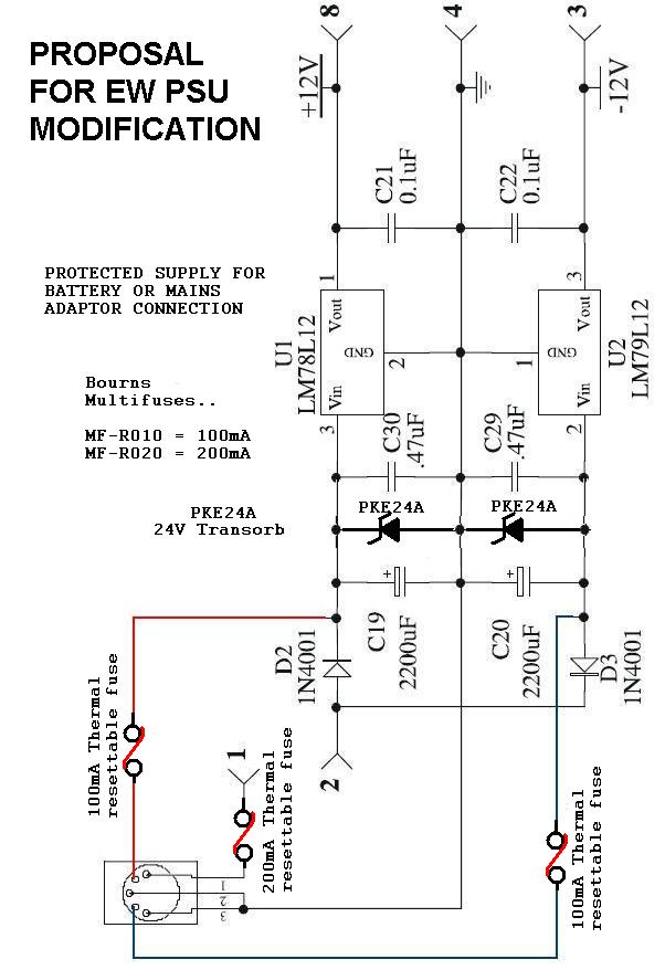
ADDED >> I advise putting a 500W 18V transorb on the input to the SMPS, and having a series resettable 250mA thermal "fuse" between the battery and the Transorb / SMPS... A unidirectional Pke series transorb will protect against reverse battery connection and overvoltage IF there is a fuse between it and the battery. <<

 Below are all the instructions you should need to get started.. You might need to add some capacitors or a simple RC or LC filter on the output of the SMPSU if you get problems with noise. … But this is all the private advice I will be giving – If you want more detail, use the TW forum! … That way the time I spend (and have spent) can de of benefit to others.

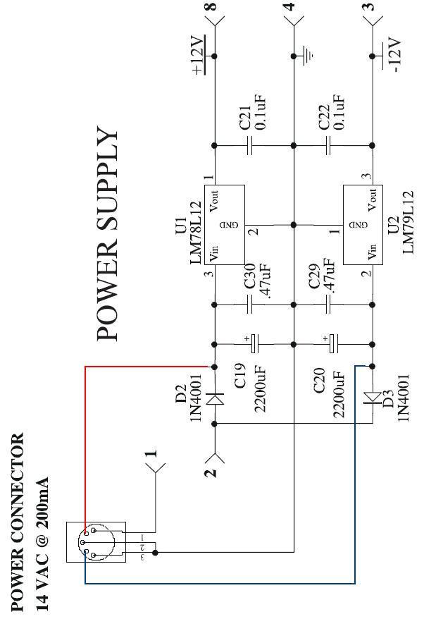
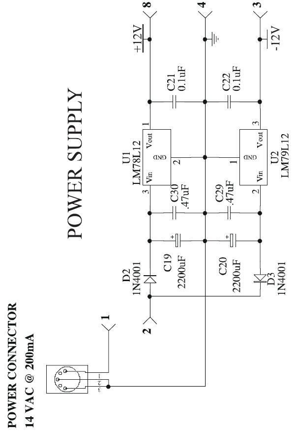
This is the regulator section inside the EW:

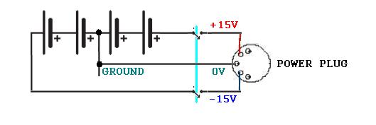
And this is the modification you must make: Cut the connection between  D2 and D3, and rewire the power socket as shown..  The power switch on the EW CANNOT BE USED! .. If you must have a power switch, you need to replace the existing switch with a double pole switch to disconnect both + and – connections!

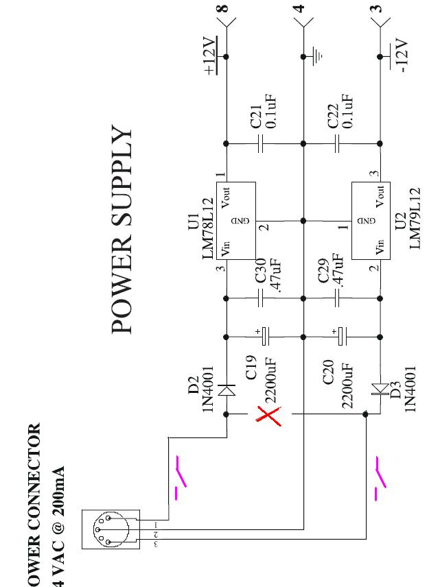
If you don’t want to cut the EW circuit board track, just de-solder the Anode of D2 and the Cathode of D3, Lift these out of the board, and solder the wires directly to them.. Or just lift one diodes leg out, and connect the socket to this and the original wire going to the switch ..

In fact, if you lift D3:K out, and put a link across the switch, disconnect the link from pin 2 to pin 3, and connect D3:K to pin 3, this may be easiest ...


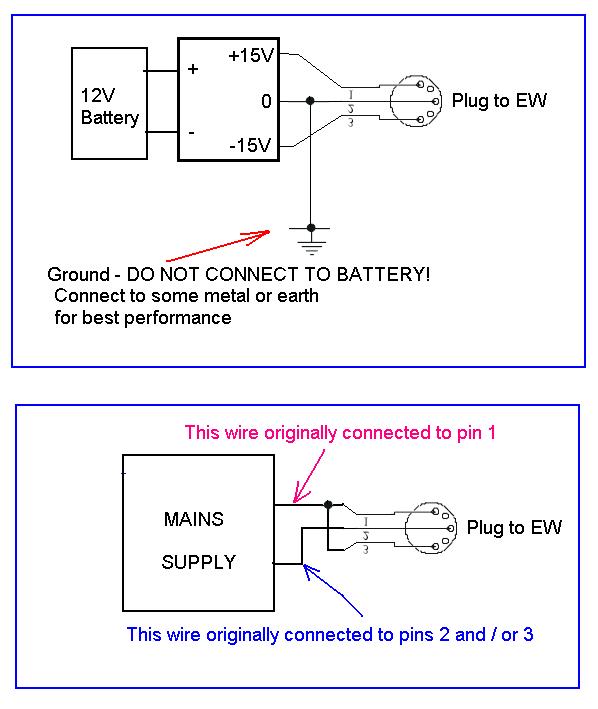
This is the wiring for the SMPS, and the NEW WIRING for the mains PSU plug..

 --------------------------------------------

A photo album has been created for this topic, please add any images there.. If anyone does actually implement this, it would be great to have some photos to guide others!

Over to the EW experts!

;-) 


Posted: 4/16/2013 7:31:19 AM
FredM

From: Eastleigh, Hampshire, U.K. ................................... Fred Mundell. ................................... Electronics Engineer. (Primarily Analogue) .. CV Synths 1974-1980 .. Theremin developer 2007 to present .. soon to be Developing / Trading as WaveCrafter.com . ...................................

Joined: 12/7/2007

Re: Grounding / Earthing..

You dont need any earth / ground receptacle..

All you need is some form of "ground antenna" to close the capacitive circuit.

A sheet of aluminium foil or space blanket, stuck to a mat, with a connection to the ground wire I have shown, or even a simple construction using a few copper pipes one can clip together to make a loop arround the thereminist (or, for that matter, a simple loop of cable or even a screened audio lead lying on the ground arround the thereminist) will give ground coupling which is more than adequate.

The best is a conductive sheet directly under the thereminists feet - A 2' by 2' thin sheet of copper or aluminium (or any metal) cut in half and both halves connected to the ground lead, and a piece of mat bonded to the sheets, so it can be folded for easy transportation is worth constructing .. One can solder directly to copper sheet, or can connect the lead using solder tags riveted to other metalss , or by soldering onto copper tape having  conductive adhesive which can be stuck to the metal sheet (the type used for EMC shielding - but it is expensive to buy a roll.. If people are interested I could sell small sections of this - probably be about 50p or £1 for enough to do the job - but rivets are more robust)

This fixation about a ground recepticle is a red herring.. Yes, if one did not have a good player ground field, linearity and sensitivity will be affected (sound will not be!) .. But many people use battery theremins without a ground, and never notice this! .. If one has even a grounded (as in, connected to the THEREMINS GROUND)  audio lead running close to (0r ideally looped 'round) the thereminists feet, you will get as good, or better player-ground coupling than most thereminists have at home or in a studio!

My H1 theremins had independent ground antennas - they were not connected to any "receptical" and relied on capacitive coupling.

Fred.

>> There is absolutely nothing "magical" or "mystical" about connection to "real" ground.. If you understand CAPACITANCE you will see that ALL such a connection is doing is increasing the area of the "ground antenna" of the theremin, so that this encompasses everything connected to ground..

If on does not have access to this connection - If you are in a concrete parking lot with no means of connecting to this "large antenna", you need to create a "ground antenna" large enough to couple about 50pF (ideally more - say 100pF which is about the average home / studio coupling) of capacitance to the player..

This 50pF will effectively be a series capacitance between the "ground antenna" and the player, The player creates a variable capacitance between themselves and the pitch  (and volume) antennas.. The coupling here is <10pF..

lets look at the kind of results you get.. With 100pF ground coupling, and hand capacitance changing from 1pF to 1.5pF (a big change, quite close to the antenna) you get a total capacitive change of 0.487734pF when you compute the series player - ground capacitance in.

If the player was physically connected to ground, you would get 0.5pF change..

Reduce the player-ground goupling to 50pF you get 0.475919pF

Reduce to 25pF you get 0.395256917pF

The further the hand iss from the antenna (the lower the capacitance), the less the effect of the seies ground coupling capacitance will have.. This means that, close to the antenna, if ground coupling is poor, the increase in capacitance "seen" by the antenna will be greater - Ant this will reduce linearity, because pitch will increase more rapidly close to the antenna.

But THE FACT is that, IT IS SIMPLE to get 50pF or better player coupling through the methods I have described - AND THIS IS ALL YOU NEED

Posted: 4/16/2013 7:32:48 AM
FredM

From: Eastleigh, Hampshire, U.K. ................................... Fred Mundell. ................................... Electronics Engineer. (Primarily Analogue) .. CV Synths 1974-1980 .. Theremin developer 2007 to present .. soon to be Developing / Trading as WaveCrafter.com . ...................................

Joined: 12/7/2007

"This is direct from the Moog "Understanding, Customizing, and Hot-Rodding your Etherwave Theremin" manual. Any help?" - ChrisC 

-posting from <original thread>  Original thread has been (justifiably) deleted by the moderators, ChrisC has re-posted his contribution below. Hopefully this thread can stay on-topic (perhaps some humor is ok ;-) and remain technical, and be of interest to those WANTING TO RUN THEIR EW FROM SOME FORM OF BATTERY SUPPLY..

Yes, thanks Chris! .. Funny how I had completely overlooked that page ;-)

Ok, the interesting thing to me is the "30mA" - This means that a cheaper SMPSU could probably be found to do the job.. We know it will certainly be less than 100mA / rail, but probably a SMPS capable of 50mA / rail will do the job.

This "circuit" is extremely crude and, quite honestly, hobbyist! .. A bit of thinking about wiring this lot, and the danger that connecting a PSU while the batteries were connected could damage the batteries - well - Let me have a stab at improving the "block of wood with a clump of batteries and a nail in it" ;-)

There are two spare pins on the power connector, so wiring connections to these should enable one to connect a battery pack directly to this connector..

As one can only plug either the batteries or the power supply in, there is no possibility of problems in this regard.

What this DOES NOT facilitate (unlike my prior proposal), is that there is no protection of any kind - Connect the batteries (OR SMPSU) up wrong and you damage your theremin.

But it does have the advantage that (If the PSU plug on the mains supply is wired the same as the socket, which I assume it is) that no modification is required to the PSU plugs wiring.

This scheme could be used with batteries or SMPSU, the power switch will still operate when the unit is run from the mains (AC) supply.

Add a couple of diodes in series with the wires, and you add the protection - you lose about 0.6V drop per diode - but I think that the protection is worth it..

I would actually redesign the EW PSU - Have a couple of 100mA resettable thermal fuses in series with the supplies, and have a couple of uni-directional transorbs to protect against reverse and overvoltage risks.. This way there is no risk and no voltage drop..


The double pole switch is optional - power could simply be disconnected by removing the plug from the theremin.

If using a SMPSU rather than batteries, a (single pole) switch between the battery driving the SMPSU and the SMPSU will be required.

Final addition..

I said I would redesign the EW PSU if I was designing this theremin -

Well, heres a modification which I think would be possible on the existing PSU, and gives protection against revers and overvoltage conditions without adding any diode voltage drop (gives about 0.2V drop across the fuses @ 50mA) ..

No, its not how I would design a PSU (A failure of one fuse on the battery input leaves 1/2 the supply still connected - not ideal) - But its the best I can do with the existing schematic, without adding an electronic current sensor and "fuse" circuit which disconnects both rails.

It should be noted that the fuses require a higher current rating than the maximum continuous current drawn - These fuses work by heating up when "excessive" current flows, and going open circuit until they cool below a lower threshold temperature (there is a large hysteresis).. It takes a while (20 seconds under normal conditions, I think) before they auto-reset.

On power up, there will be higher current as C19 and C20 charge - I have not looked closely at this for the EW, but it needs to be borne in mind as, if too low a value rating, the fuses may heat up enough during this charging phase to trip.. (this is unlikely as they take a long time to 'blow') Also, if a SMPS is used, it needs to be able to cope with the brief over-current charging these capacitors will produce. the DCW08A-15 is rated as being able to tolerate output short-circuit, and operate in "hiccup" mode - so this should be able (I think) to drive these capacitors and charge them in "hiccups" if needed... (I have not tried this - I usually have a seperate current limiter on my PSU designs )

You could put standard diodes (1N4001 to 7s for example) instead of Transorbs to get reverse voltage protection but not overvoltage protection - but if modifying the board, I think the transorbs are worth fitting.. With transorbs fitted, I think the 200mA fuse is needed - I personally think that this level of minimum protection should be compulsory on all electronic products - failure of power supplies and overvoltage events are common - IMO, Product should not be destined for landfill due to the easily preventable concequences of such failures - Also, fitting such minimum protection would prevent the possibility of destroying a theremin by plugging a 110V adaptor into a 220V supply, as people do!

To me, such careless disregard for the possible scenarios is not excusable - Yes, manufactures must cut costs in order to compete, but a few pence ? .. Making such protection compulsory is IMO the best solution, as it would create a more level playing field.. Everyone would be forced to spend those few extra pennies!

This is my proposed "best solution":

Posted: 4/16/2013 9:52:12 PM
FredM

From: Eastleigh, Hampshire, U.K. ................................... Fred Mundell. ................................... Electronics Engineer. (Primarily Analogue) .. CV Synths 1974-1980 .. Theremin developer 2007 to present .. soon to be Developing / Trading as WaveCrafter.com . ...................................

Joined: 12/7/2007

Even in the most hostile environments, Buskers will find a way!  ;-)

Posted: 4/16/2013 10:14:14 PM
ChrisC

From: Hampshire UK

Joined: 6/14/2012

"This is direct from the Moog "Understanding, Customizing, and Hot-Rodding your Etherwave Theremin" manual. Any help?" - ChrisC  -posting from original thread

Yes, thanks Chris! .. Funny how I had completely overlooked that page ;-)

That posting from original thread!

Posted: 4/16/2013 10:18:33 PM
FredM

From: Eastleigh, Hampshire, U.K. ................................... Fred Mundell. ................................... Electronics Engineer. (Primarily Analogue) .. CV Synths 1974-1980 .. Theremin developer 2007 to present .. soon to be Developing / Trading as WaveCrafter.com . ...................................

Joined: 12/7/2007

"That posting from original thread!" - ChrisC

Thank you Chris!  - I was only able to "transport" my postings, alas, yours and nieradka's (and my reply to nieradka, which is effectively covered in the above) got left behind in the debris..

Fred.

Posted: 4/16/2013 10:58:01 PM
FredM

From: Eastleigh, Hampshire, U.K. ................................... Fred Mundell. ................................... Electronics Engineer. (Primarily Analogue) .. CV Synths 1974-1980 .. Theremin developer 2007 to present .. soon to be Developing / Trading as WaveCrafter.com . ...................................

Joined: 12/7/2007

RE: Grounding / Earthing :: vs :: EW TRM Instructions.

I must just say, in relation to the above instructions in  "Understanding, Customizing, and Hot-Rodding your Etherwave Theremin" that one DOES NOT need to connect to a "real" earth, or plumbing, or metal framed building! - These instructions are, quite simply, WRONG! (or at least not comprehensive - there are other things one can do !)

Yes, you do need a "ground antenna" and connection to those items is the easiest and simplest IF one has these available - But if they arent available, the instructions I give in my above postings are just as effective!

This is not based on theory alone! I have had 16 one-stick theremins running simultaneously in what is probably about as hostile an environment capacitively as one can find, and these theremins had good linearity and were not "grounded" - They each had a "ground antenna" - Originally consisting of a length of wire running on the floor under special adhesive tape for covering wires, and then when these wires were ignorantly removed by an electrician, I used aluminium foil inside the plinths the theremins were standing on.

I have since built other one-stick theremins without connection to "real ground" - A couple of these were fitted in a transportable maize which is taken to fun fairs, where they act as a warning of impending doom when people approach them ;-) - these were battery powered, but their musical "abilities" were not relevant (they were not played - just deliberately made a deep modulated growling sound which turned into a horrible "scream" as people approached the hidden unit) - But inclusion of a small "ground antenna" connected to a metalized mat on the floor gave more than enough coupling had I needed it to be musical. I have tested many theremins using a sheet of copper as the only ground, and there are no problems. (once played one at a friends open-air party with a blues band .. only did this because if I hadnt, he wouldnt have lent me the money I needed to survive the month - I had just spent all my money on the 16 theremins and not recieved payment for them yet .. Not happy about playing prototype theremin, or playing at all for that matter with my lack of skill.. I got away with it because all the other "musicians" were as appalling as I was - I ended up swapping the theremin for the tea-chest one-string bass, which I played better than the owner, and I think he may have played the theremin better than me.. and it was linear enough for a complete newbee to play, and only had a long audio cable arround where the player stood - Sadly,  we both were "forced" to  give up when a woman with a bass guitar and powerful portable amp, who couldnt play a note in tune, took over and drowned us both out!  ;-).

I KNOW it works, and works well! - You do not need to bash metal stakes into the ground, and running a long lead to the nearest grounding point is likely to be a lot less effective than just looping this lead on the ground  'round the player! - its capacitive coupling of high frequencies you need, you do not need a galvanic connection - If you can easily get a local galvanic connection to ground, great! If not, dont panic! All you need is a towel, a wire, and some aluminium foil !    Only the towel is essential!  ;-)

Fred.

RE: The Towel :

" More importantly, a towel has immense psychological value. For some reason, if a strag (strag: non-busker) discovers that a busker has his towel with him, he will automatically assume that he is also in possession of a toothbrush, face flannel, soap, tin of biscuits, flask, compass, map, ball of string, gnat spray, wet weather gear, space suit etc., etc. Furthermore, the strag will then happily lend the busker any of these or a dozen other items that the busker might accidentally have "lost". What the strag will think is that any man who can busk the length and breadth of the galaxy, rough it, slum it, struggle against terrible odds, win through, and still knows where his towel is is clearly a man to be reckoned with."

Posted: 4/17/2013 4:42:29 AM
FredM

From: Eastleigh, Hampshire, U.K. ................................... Fred Mundell. ................................... Electronics Engineer. (Primarily Analogue) .. CV Synths 1974-1980 .. Theremin developer 2007 to present .. soon to be Developing / Trading as WaveCrafter.com . ...................................

Joined: 12/7/2007

OFF TOPIC!  RE: Taking a break.. :

I have spent far more time on this matter than I had intended, so I am now leaving this thread (and probably wont even look at TW for a few weeks).. I am sure that any matters which arise can be dealt with by EW experts here - I have at least given you a block of wood with a nail in it, and hopefully enough in the "files" to enable you to turn this into what you need.

The above is just so brilliant I had to nick it! ;-) Thanks Dewster!

Goodbye.

Posted: 4/27/2013 5:00:51 AM
bisem

From: Pittsburgh, Pennsylvania

Joined: 1/1/2011

Re: Grounding / Earthing..

Remember this article on TW?  http://www.thereminworld.com/Article/14386/wavingboxs-ultimate-busking-theremin

This guy has pictures of himself busking on concrete.   On his website in describing the construction of his portable EW he mentions the following: "3 metal sheets added in the bottom of the case to reduce the undesirable effects due to the grounding absence, everything has it's place....the theremin is now fully autonomous thanks to Thierry Frenkel.  He's The man of the situation in every technical theremin challenge!!!"

The travel case he has is very small and one certainly can't see any metal plating in the pictures: http://wavingbox.over-blog.com/25-index.html  Does anyone have any idea how he did it?

Posted: 4/27/2013 7:58:34 AM
Thierry

From: Colmar, France

Joined: 12/31/2007

The plate (painted in brown) on which he installed all these plastic clamps for the antennas is massive inox steel. You can see a grounding wire leading from the top left screw to the amplifier. Another grounding wire (not visible on the pictures) connects all 4 speaker chassis to ground. 

When Thomas sets up his mobile theremin, the (upper) speaker side of the (then closed) travel case points towards the public while the bottom side with the inox plates points towards him (his legs). The capacitance between these plates and his legs is sufficient to close the grounding circuit.

Thomas lives only a few miles away from me in France and he visited me several times so that I could help him to develop this virtual grounding solution.

You must be logged in to post a reply. Please log in or register for a new account.