My New Year gift to TW: A new theremin circuit

Posted: 10/23/2015 12:34:40 PM
Thierry

From: Colmar, France

Joined: 12/31/2007

I can tell you what happens in LTSpice when you try to simulate the circuit with these 1000 times too high resistor values : The same as in reality. The oscillators simply won't start because the current flow is ways tooo limited from both sides, the source and the drain side. As soon as some resonant circuit would even accidentally flow in the LC tank, already minimal currents would cause a too high voltage drop along R11/R41 and R12/R42 ( U = R x I ) so that the source voltage of the FET would go up and drive the FET into cut-off, while the drain voltage would go down below meaningful working parameters.

The only positive thing is that with such high resistance values, the current flow was so limited that you didn't damage anything else wink

Posted: 10/23/2015 7:39:20 PM
xoadc

From: Moncton, New Brunswick, Canada

Joined: 4/24/2015

HOORAY!  sound has been achieved!


Posted: 10/25/2015 8:14:56 PM
dewster

From: Northern NJ, USA

Joined: 2/17/2012

I just bought some J113 NJFETs from DigiKey.  -0.5V to -3V VGS, 2mA minimum IDSS.  Only 25 cents each (quantity 25).  Haven't tested them extensively, but two picked at random are Clapp oscillating on the test jig at ~2MHz, ~40V swing at the plate antenna, VCC = 3.3V.  They would likely work for this project as well.  The J113 seems quite available and easy to obtain.

Posted: 10/25/2015 8:39:06 PM
Thierry

From: Colmar, France

Joined: 12/31/2007

Thank you, dewster, for that hint. I'll order some and test these in the thierrymin circuit although an Idss of 2mA seems a bit low to me for that application, since a low Idss means most times also a low amplification factor. But I'd like to be proven wrong.

Posted: 10/26/2015 5:59:57 PM
dewster

From: Northern NJ, USA

Joined: 2/17/2012

I actually breadboarded the oscillator with the J113.  It works very much as it Spices:

http://www.mediafire.com/download/c2larz505ad6obn/thierrymin_osc_j113_2015-10-26.asc

Notable differences: 

R1 s/b 470 Ohms

C1 s/b 150pF

C2 s/b 1500pF

L1 s/b 1mH

VCC s/b 6V

I didn't include isolating C3 & R2 on the breadboard as this is the only oscillator on it.

Sim shows 10.5Vp-p at the antenna, I'm seeing 15.5Vp-p.

I tried two J113s and they both worked.  Tried an MPF102 and it also worked but at a lower amplitude.  

I'm seeing pretty much this exact same waveform at the antenna (through a 1pF cap) so the JFET is really loading the bottom section of the swing.  But it seems pretty stable with the scope delayed 50ms, I'm sure it's stable enough for Theremin work.

The J113 spec sheet says the Gate to Drain (and Gate to Source) on / off capacitance is 28pF / 5pF.  Wondering if the pronounced bottom rounding is caused by the switching in and out of 23pF?

[EDIT]

Not surprisingly, it seems to be associated with JFET conduction.  Interesting the reversal in source current.

Posted: 11/15/2015 9:01:31 AM
myxl

Joined: 11/15/2015

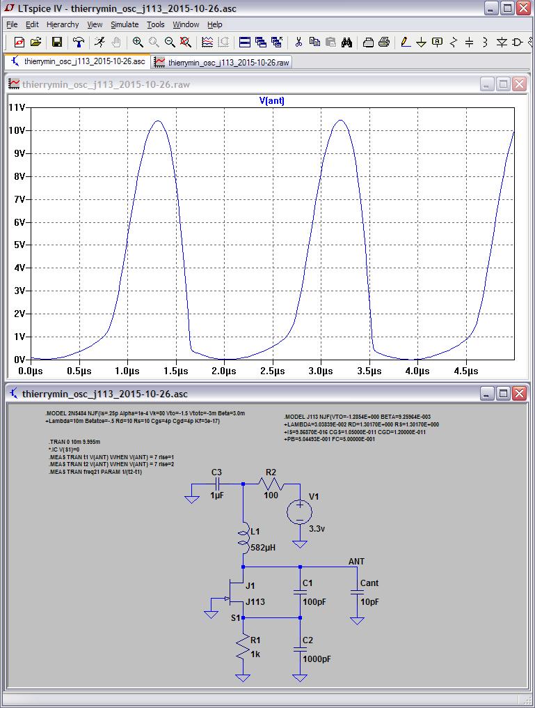
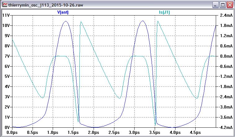
Hello all, I've been stalking this thread for a while and am finally embarking on my theremin building odyssey, but I've just got a couple questions.

First if anyone has one of these on a breadboard, I'd very much like to see a picture of it as I'm trying to figure out the layout without messing around with ESD components (speaking of which, are those safe after being soldered on or is handling of the board verboten at that point?).

My next question regards what to do with the AUDIO output. I saw it mentioned that the Coke bottles used the LM386 amp, so for that would it be hooked up as in this typical app from the sheet (with Vin=AUDIO, Vs=6V, and an 8 ohm speaker on the output) or would I need more gain than the 20 provided by this application? (The output is an aspect that I must ignorant I'm wholly ignorant on as this is my first time working with sound and I don't know what the output will look like, much less what it should to produce sound after going through the amp)

Just as an aside about the application, I'm trying to build it as part of a circuit for a school project using a regulator with an enable that will allow me to provide the theremin power based on the output of two D F/F that will latch based on the user producing a particular motion followed by another within a time frame of a couple seconds. The theme of the project was measuring motion (and we had to use an accelerometer for it), and after learning about the theremin this summer I thought it would be well suited to continue the theme into what the motion detection would instantiate.

Thanks!

Myxl


Posted: 11/15/2015 5:38:29 PM
oldtemecula

From: 60 Miles North of San Diego, CA

Joined: 10/1/2014

myxl: You want someone here to invent and design your school project? You threw out some ideas but the ideas are disconnected, I am not sure if you want to detect motion or measure motion. If you want to “detect motion” the simplest method is passive infrared. A theremin could work but most of the time it is best left as a simple musical instrument. To “measure motion” you will need a solid reference which a theremin is not. Maybe an engineer will chime in, but I doubt they would interfere with your studies. Analog is a fading Art, we need you to succeed with a long journey ahead of you. In the 80's the 4013 flip-flop was one of my favorites logic chips to design around.

Christopher

Posted: 11/15/2015 6:08:57 PM
elmo7sharp9

Joined: 10/11/2012

Here is a breadboarded layout that worked for me. Criticism of my re-useable LONG wiring will fall on Deaf Ears - I knocked this one up in a hurry, and it worked. You should, ideally, cut wires to the exact length needed and install them neatly.

Wide spacing was used wherever possible, for example - the FETs have an unused strip between each leg.

Each oscillator is on an "outside" strip, with the mixer in the middle, to minimise unwanted interaction.

The LM386 circuit should work as-is. If you need more gain, connect an electrolytic capacitor between pins 1 & 8 (Look again at the Datasheet).

Breadboarded

Posted: 11/15/2015 8:30:23 PM
Thierry

From: Colmar, France

Joined: 12/31/2007

Even the default gain of 20 will be too much, it's important to put the 10k potentiometer between the Thierrymin and the LM 386 in order to not overdriving the latter.

Posted: 11/15/2015 8:52:17 PM
dewster

From: Northern NJ, USA

Joined: 2/17/2012

I would suggest you try running the LM386 directly off the unregulated 9V battery instead of the regulated 6V.  Might get a bit more wattage, and the large speaker current would be somewhat isolated from the oscillators.

You must be logged in to post a reply. Please log in or register for a new account.