Moog Music Theremini Reviews

Posted: 8/12/2014 3:39:10 AM
krellmusician

From: Hell's Quarter Acre, New England, USA

Joined: 12/7/2013

Uh, I don't mean to interrupt this spirited discussion.  I've skimmed the last few pages with the intent of reading them in detail later on.

I purchased one of the first available Thereminis back after their availability was initially announced (from Kraft Music in early June).  I played with it a bit in the first few days, and then the demands of work, garden work, household work, and work on two "real" Theremins (EWS with the Plus field upgrade and Thierry's special board, and the restoration of the kit-based pseudo-Troubador I posted about last November) have taken me away from it.

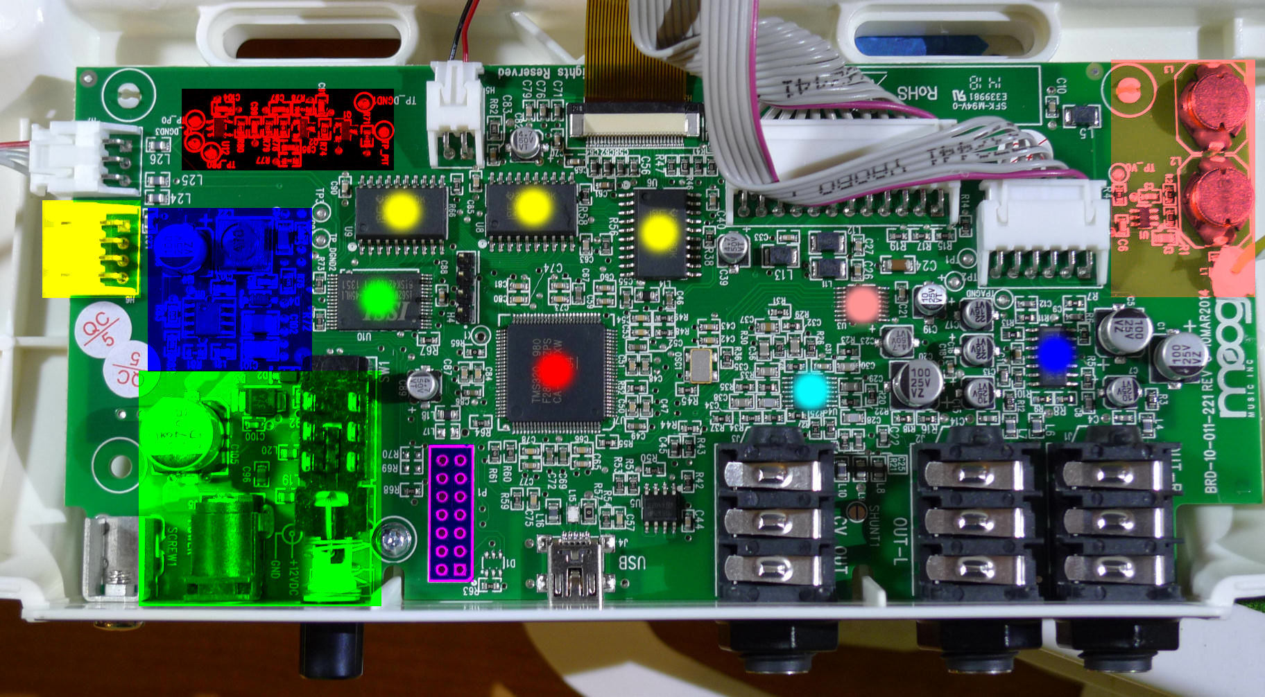
Dewster's pictures brought me back, having saved me the trouble of opening up my own unit (at least for the moment...).  I noted Ilya's schematic of the somewhat sparse proximity-detecting front-end, and the three-wire ribbon running from the pitch board to the main board.  But am I the only one who noticed the four-pin connector lying UNUSED next to the pitch board connection?  Doesn't anyone have any curiosity as to what purpose this serves, or was intended to serve? Perhaps it's there for some future hardware/software upgrade that may solve (at least in part) some of the issues discussed herein.

You may argue that I jumped the gun when I bought the Theremini so soon, and in fact my intent when the device was initially announced was to ignore it completely.  But I have several Casios around the house; my first Theremin (which never quite worked, or at least not how I expected it to) was the SWTPC kit from the early '70s; I've managed to assemble a Theremax and get it sort of working (it will be modded and recased soon), with another kit waiting to be assembled; I've put together several of the original Jaycar 2000 Theremins (stock and with custom mods, including Max's); I have the Jaycar MIDI Theremin (now THERE is a POS if ever there were one) in partial completion, and what is either the Mini Theremin Mk II or the current Mk II, as yet untouched; I have the two Theremins mentioned above, plus a fully assembled and functional quarter-sawn-oak EWS (unmodified); and I have a couple of the Urs Gaudenz Open Theremin UNO boards to feed my Arduino habit.  All of which is by way of saying the following:

(1) I'm not much of a Theremin player (yet), precision or otherwise, but I have the tools in house to become reasonably competent with practice.

(2) I'm inclined to use the Theremin as a texture and/or effect, and I have the tools in house to make that a reality as well.

(3) I never saw the Theremini as a means to attain (1) but as a possible addition to my arsenal for (2), especially with the USB MIDI output and the Animoog incorporation.

(4) I don't see the Theremini as a fait accompli, but rather as a challenge -- NAY, a GAUNTLET cast down hard before me -- to make it a potentially better musical device, if not an actual instrument per se.

(5) I write software for a living and the Arduino and similar platforms are among my hobbies, so software changes and upgrades, as well as custom code, don't concern me.

So I see the Theremini more as R&D and modification fodder than as a baguette or a turd.  It's the musical equivalent of Charlie Brown's Christmas tree; if I wave my hands over it long enough and hard enough, maybe I can make it something pretty and useful, even if only to myself.

Anyway, any speculation about that unused connector?

Posted: 8/12/2014 9:13:11 AM
FredM

From: Eastleigh, Hampshire, U.K. ................................... Fred Mundell. ................................... Electronics Engineer. (Primarily Analogue) .. CV Synths 1974-1980 .. Theremin developer 2007 to present .. soon to be Developing / Trading as WaveCrafter.com . ...................................

Joined: 12/7/2007

"Anyway, any speculation about that unused connector?"

Yeah, I recon its an interface to the infinite improbability drive.

Posted: 8/12/2014 6:33:54 PM
dewster

From: Northern NJ, USA

Joined: 2/17/2012

Sitting here with the laptop in an old style inn on a tiny lake in Flat Rock, NC - time for some reverse engineering!

"Spray Painted" colored round spots above, from LEFT to RIGHT:

GREEN : IS62WV1288DBLL - 128k x 8 CMOS static RAM

YELLOW : LVC574A - Hex DFF w/ OE

RED : TMS320F28069UPZPS - 90MHz, 32 bit TI Piccolo DSP w/ 32k x 16 boot ROM, 128k x 16 Flash, 50k x 16 SARAM, 12 bit ADC

AQUA : L324 - Quad OPAMP (?)

PINK : AK4386 - 24 bit delta-sigma stereo DAC

BLUE : TL074AC - Quad FET input OPAMP

==============

Colored rectangular regions above, from RIGHT to LEFT:

PINK : Volume oscillator

PURPLE : DSP JTAG debug port

GREEN : Power input

BLUE : 12V => 3.3V step down switching converter?

RED : Pitch oscillator processing / conditioning?

YELLOW : H6 - secondary pitch oscillator connection?  (Pure guesswork.)

==============

If the blue region is indeed a switching supply, it seems to be positioned uncomfortably close to the pitch oscillator input.  Though I suppose with the pitch oscillator being buffered, the level at this point is fairly immune to interference.

The red region has a 5 pin IC and two transistors.  It's not clear to me what it does but there are test points labeled "TP_P0", "TP_PRO", and "TP_PIT".  The first is likely the raw oscillator input, the second may be for the secondary pitch oscillator input (???), and the third seems to be the processed pitch oscillator signal.

Kind of strange that yellow H6 connector is populated but unused.  I wonder (wild speculation) if they are planning on using the same controller board for their rumored "pro" model Theremin and need the input for that?  H6 seems to have power and ground going to it on the outer pins.  The extra pin could be used either as an input to the oscillator or as an output, though if any of this has a grain of truth I'm wondering why they didn't just use H6 for both the Theremini and the fabled pro model?

Posted: 8/12/2014 6:45:02 PM
Touchless

From: Tucson, AZ USA

Joined: 2/26/2011

I like the way you explore, open to possibilities and not calling each step rubbish. Are you going to clean all that paint off before you return it for a refund?

T

Posted: 8/12/2014 6:56:58 PM
dewster

From: Northern NJ, USA

Joined: 2/17/2012

"I like the way you explore, open to possibilities and not calling each step rubbish."  - Touchless

Ilya stole my thunder by tracing it out (which is really great, and not that I don't trust his expertise, but I want to confirm his analysis) and not to pile on, but Moog Inc.'s choice of oscillator here is pretty much crap, particularly for the pitch side.  The addition of one tiny capacitor would boost the voltage swing quite a bit (~10x) and the addition of a second inductor would boost it even more (~2x).

The UI is little more than a preset selector.  I'd probably take more of a shine to the Theremini if it gave me at least some direct control over the internal Animoog engine settings.

"Are you going to clean all that paint off before you return it for a refund?"

Ha ha!  Since I opened it I won't be sending it back to the retailer.  Not sure if / when I'll be jettisoning it, maybe hold onto it for a bit to see what firmware updates might come down the pike.  But I suspect that no SW band-aid can really fix the bad HW in there.

Posted: 8/12/2014 7:10:27 PM
randy george

From: Los Angeles, California

Joined: 2/5/2006

Over at the Moog Music website, there is now an adapter available for people in the USA that want to use their Theremini with a microphone stand. It costs $3.95.

http://www.moogmusic.com/products/accessories/theremini-mic-stand-adapter

There must have been some serious penny pinching going on when the Theremini designers were sourcing components. The enclosure must have been cheaper to build with a 3/8" threaded fitting rather than a 5/8" fitting. Perhaps Moog Music wagered that the savings would outweigh the cost of customer dissatisfaction and inconvenience...

Edit: Thinking further on this...  It is only inconvenient for USA customers. Perhaps that is a very small section of the target end user demographic for the Theremini.  The point that the adapter is not included in the Theremini package is a bit sad.  It quietly screams, "I don't care about you, customer! I just care about your money."


Posted: 8/12/2014 8:45:18 PM
dewster

From: Northern NJ, USA

Joined: 2/17/2012

I concur with ILYA's pitch oscillator analysis.  C2 is physically larger than C3, perhaps they are the same value but C2 is higher voltage (for ESD)?  Or perhaps they are sized to get approximately the same swing at both ends of the inductor L3?  Ah, at this point who cares.

Posted: 8/12/2014 8:56:19 PM
FredM

From: Eastleigh, Hampshire, U.K. ................................... Fred Mundell. ................................... Electronics Engineer. (Primarily Analogue) .. CV Synths 1974-1980 .. Theremin developer 2007 to present .. soon to be Developing / Trading as WaveCrafter.com . ...................................

Joined: 12/7/2007

Hi Dewster,

Just a couple of points:

1.) I checked Ilys's analysis when he first posted it - What struck me was that it looked awfully similar to an oscillator I had seen recently when examining some schematic linked from TW, but I couldn't remember which.. Anyway, AFAICS the schematic drafted by Ilya is spot-on..... And I found where ive seen it before - its the same as on the UNO.

I am not at all familiar with these SMD dual inverters, so checked them out - was quite surprised at their high output drive capability! - But they only have 2kV HBM ESD protection.

2.) Looking at the blue section (used Photoshop to try to enhance image, but couldn't disclose IC part number - did enhance tracks etc though) I think you are right - it is a SMPS of some sort.

3.) The red section does appear to be related to the pitch oscillator, and is a bit of a puzzle - I wonder if its in fact a mixer and filter section? - takes pitch oscillator and reference from somewhere (DSP?), and pipes back the difference to the DSP..

Dewster, I fear I might be barking.. Please could you confirm / refute my analysis.. To me, it seems that with this type of oscillator, the antenna voltage is limited to the supply rails (0 to +5V) as the antenna is connected directly to the gate input, and apart from anything else, these inputs are diode clamped to the rails.. Would this not mean that the UNO is subject to the same front-end limitation that the theremini is, and that the linearization gained by the clever offset action is being thrown away? - Perhaps it was you who noticed the linearizing action of offset, and just assumed others incorporated offset for that reason, when in fact none of us ever noticed it until you revealed it?  - or am I missing something?

Fred

(I also wonder about L2 - is this perhaps fitted not so much to prevent incoming HF, but to prevent radiated RFI? I imagine it quite possible for the drive to cause the input side to exceed the rails slightly, causing clipping of the waveform via the diodes, resulting in higher harmonics being generated and needing some attenuation before the antenna..)

"Ah, at this point who cares."

LOL ;-)  ... I dont ;-) ... But I couldn't resist your analysis - your postings are always an interesting read! (even ones on matters like Hive, which, to me, could almost have been produced by some algorithmic gobbledygook generator ;-)

Red Area:

( Is U12 perhaps a single XOR?) - in which case TP_PO would be the pitch osc, TP_PRO would be Pitch Reference Oscillator and one could guess that TP_PIT would be the difference out (Pitch Interval Time?)

Also, PO is taken to the DSP via R64 if I trace it right. This all confirms (almost) that the front-end topology is not EW like in any way, but more comparable to the UNO.

-------------------

Assuming  the above, The theremini could be made usable I think. One has a digital theremin development kit here - the area which is crap is all the analogue stuff and probably  the software needed to filter / correct this.

Fix the analogue (replace the oscillator at least - if there is excessive hardware filtering on the mixer, this may also need fixing) and re-write the software, and one may end up with a usable instrument.

But without schematics / mapping / code, only Moog can do the re-write - unless someone is willing to spend the time reverse engineering the lot and re-writing it all.... Which wouldn't make any sense cause if they can do that they could more easily buy a MCU or DSP or FPGA DK and do the job better.

---------------------

Question:

Is tuning performed purely in the DSP (numerically) or is the reference oscillator (T__PRO) frequency changed? - I am thinking that if TP_PRO is fixed, then there could be a lot of variation in performance between one theremini and another in the area of linearity and latency.. I assume TP_PRO frequency must change..

-------------------

Where I could be wrong:

As I said before, my experience with low antenna voltage leads me to believe that non-linearity and lack of far-field sensitivity are reduced if voltage swing on the antenna is increased above some level.. However, I also stated that I do not know why! - I put the reason down to the increased influence of interferer's on low voltage antennas, but this does not fully explain anything.

In simulations, I see no difference between low voltage and high voltage oscillations on electrodes in terms of far-field sensitivity and linearity... In practice though, low voltage electrode (antenna) swing fell far short of the behavior the simulations predicted, whereas high voltage swing behaved as predicted.

When I dont fully understand why something works or doesn't, I get uncomfortable - I can think of some mechanisms that make high voltage "better" but cannot explain why so much better, or why low voltage is so much worse. Based on experience, I would not want < 20V P-P on an antenna, and prefer >50V P-P, but have no scientific theoretical basis for this... And I therefore have no theoretical grounds that I am aware of to declare that increasing the theremini antenna voltage will improve far-field sensitivity or linearity or anything else.

I certainly know that higher antenna voltages give lower noise, lower instability, and therefore require less filtering etc - theory on this is simple and sound.

Posted: 8/13/2014 2:12:58 PM
ILYA

From: Theremin Motherland

Joined: 11/13/2005

"C2 is physically larger than C3, perhaps they are the same value but C2 is higher voltage (for ESD)" -- dewster

or C2  has special characteristics, the negative temperature coefficient, for example (to though somehow compensate the positive coefficient of ferrite).

 NTC = different dielectric material = increased size.


Posted: 8/13/2014 7:24:41 PM
dewster

From: Northern NJ, USA

Joined: 2/17/2012

"...its the same as on the UNO."  - FredM

Yes, same topology.  Though from my calculation the Theremini oscillator uses smaller capacitances.  The UNO uses ~150pF on the antenna side and 220pF on the drive side, the series combination of which is ~89pF.  The Theremini series capacitance is around 30pF.

"Please could you confirm / refute my analysis.. To me, it seems that with this type of oscillator, the antenna voltage is limited to the supply rails (0 to +5V) as the antenna is connected directly to the gate input, and apart from anything else, these inputs are diode clamped to the rails.. Would this not mean that the UNO is subject to the same front-end limitation that the theremini is, and that the linearization gained by the clever offset action is being thrown away? - Perhaps it was you who noticed the linearizing action of offset, and just assumed others incorporated offset for that reason, when in fact none of us ever noticed it until you revealed it?  - or am I missing something?"

Yes, the antenna swing is limited to the supply rails.  UNO linearization is obtained via offset heterodyning with period measurement, which is unrelated to antenna voltage swing.  And I didn't originate this method of linearization, the first time I saw it was in the UNO, but I have studied it with my antenna / hand capacitance formula in a spreadsheet.

"(I also wonder about L2 - is this perhaps fitted not so much to prevent incoming HF, but to prevent radiated RFI? I imagine it quite possible for the drive to cause the input side to exceed the rails slightly, causing clipping of the waveform via the diodes, resulting in higher harmonics being generated and needing some attenuation before the antenna..)"

If L2 has significant inductance it could increase the antenna voltage some.  I don't have a clue as to why it's there, except for that, or for as you suggest harmonic suppression.  Interesting the FCC note on the bottom of the Theremini.

"( Is U12 perhaps a single XOR?)"

Fascinating!  I haven't traced it out, but I imagine the two transistors could be a third order LPF.  If so, then the claim of "real heterodyning" going on in there would be accurate (even if the voice isn't generated that way).

"Is tuning performed purely in the DSP (numerically) or is the reference oscillator (T__PRO) frequency changed? - I am thinking that if TP_PRO is fixed, then there could be a lot of variation in performance between one theremini and another in the area of linearity and latency.. I assume TP_PRO frequency must change.."

If they are heterodyning, then TP_PRO is likely a counter or PWM output from the DSP, the frequency of which is set at the first step of calibration, where you get away > 4' and it counts down for 5 seconds.

"As I said before, my experience with low antenna voltage leads me to believe that non-linearity and lack of far-field sensitivity are reduced if voltage swing on the antenna is increased above some level.. However, I also stated that I do not know why! - I put the reason down to the increased influence of interferer's on low voltage antennas, but this does not fully explain anything."

Funny, I've been contemplating this conundrum myself and don't have a good answer.  Though the main "interferer" that high antenna voltage overcomes could be the internal noise of the oscillator?

You must be logged in to post a reply. Please log in or register for a new account.