Etherwave maximum input voltage

Posted: 6/3/2016 11:42:33 AM
xtheremin8

From: züriCH

Joined: 3/15/2014

cristopher wrote: "This new one I am going to see if I can break it." 

don't overdo it, but hope it's possible, i would love to see a picture of the innards. 

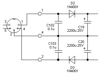
another question that occurred to me, while going through the ew schematic and thinking about those who build it from scratch, is: would it make sense to omit the onboard power regulation and use a bipolar power supply instead? like this one: bipolar power supply

or is this plain stupid?

Posted: 6/3/2016 3:20:34 PM
oldtemecula

From: 60 Miles North of San Diego, CA

Joined: 10/1/2014

xtheremin8,

That is the best information I have seen contributed at TW in a long time. Sure it will work and it appeals to my thought that all theremin designs should be done in a modular fashion. While I have my new kit EWS PC board out on the bench I want to see how much current it actually uses and the affects of a voltage direct to the circuits between 10v to 12v bypassing the on-board regulator. This is for no other reason than I want to know.

How to achieve earth ground using that alternate power supply is always an issue as my best sounding speakers are amplified computer speakers. They have great acoustic development qualities. Here in the states the earth ground is always available through a third pin on the wall plug.

My new EWS kit wood box has Plus holes already drilled which is kool. I am wanting to modify the box to look a little bit different, dropping the power cord out the bottom is an idea instead of a tail off the back. A lady should never show her tail unless a Kardashian. Bless me Father, I slept with the PCB last night.

Christopher

 Edit: Most likely that Jameco 12vac @ 1000 ma would have a an average voltage at 30 ma load of more than 2 volts above the EWS 12v regulator voltage. This is engineer stuff, I would need to bench test it. (~17v unloaded)

Posted: 6/3/2016 5:41:59 PM
dewster

From: Northern NJ, USA

Joined: 2/17/2012

Not sure how they'd get the ground in through a barrel connector, but it's too bad there aren't more three pin wall wart options.  You can bring the ground in via an IEC connector, but that brings the AC voltage in as well, along with all the danger and UL certification hassles. 

In the past I've used 12VAC transformers to provide 12VDC, but if you pull too much current you'll pull the ripple through to the regulated side.  Use too high a voltage transformer and regulator heating becomes more of a problem.  I would recommend always putting heatsinks on the regulators, I don't see this enough - those newfangled solderable regulators that use the PCB as heatsink have caused all kinds of thermal issues in newer stuff.  Even the FPGA board I'm targeting employs them, and heat is a real problem.

Posted: 6/3/2016 6:09:18 PM
xtheremin8

From: züriCH

Joined: 3/15/2014

two prongs,three prongs.. thanks tesla for ac.

 rereading thierrys's second post on this thread about grounding etc. european wallwarts have just two prongs, ground is by the amp, mixer provided.  i spent last summer some time with my etherwave and a non grounded small amp (line6 spider) in a remote area. no way to get it working properly, until i used a car charging cable, that one with big clamps, and clamped that between the jack (a metalic neutrik) and that ground-screw for the turntable at the back of the stereo. i thought about using a unused three prong power plug and just use the ground connected to a cable with a crocodile-clamp, to be prepared for another poor grounded situation. 

sadly, a local music shop is closing down & now he sells all instruments and lots of stuff like din plugs etc. for cheap. just bought a bunch of microphone nuts, i use them instead of the expensive atlas solution. my new etherwave-board should arrive soon, so i'll have my old one for experiments. since i need a second power supply too, i'll build one myself. power transformers are plenty around at the local thrift-store, etc. it just takes some efforts to find a good one. 

edit: dewster, good points of mentioning the danger of electricity. even 500mA can become letal, so i was told by a old electrician. 

Posted: 6/3/2016 6:52:04 PM
ILYA

From: Theremin Motherland

Joined: 11/13/2005

"or is this plain stupid?" - xtheremin8

The bipolar power supply with built-in regulators is a nice choice because of:
1. the heat source is removed from the theremin,
2. as a rule, such the power supplies have best characteristics than the EW's (usually they use a bridge rectifier and large capacitors).

The best option is a +-15V bipolar power supply (with built-in regulators) for regular EW schematics: the mild heat next + double regulating.

In my case I used an adapter from the old equipment, adding 7815/7915 regulators inside it .

Posted: 6/3/2016 7:03:04 PM
ILYA

From: Theremin Motherland

Joined: 11/13/2005

And a minor modification of EW  is required  -- separating positive and negative nets (individual power lines for D2 and D3) .

Posted: 6/3/2016 7:52:51 PM
oldtemecula

From: 60 Miles North of San Diego, CA

Joined: 10/1/2014

ILYA 11/13 is my birthday, send me a greeting. (-'

Being I am going to route power out the bottom of the EWS box here is my din pin-out.

Pin 1 and 3 are AC while pin 2 is earth ground tied to pin 1 on the PCB. 120 volt to 14 vac setup. Viewing the PCB female side.

The old hot-rodding PDF shows earth as Pin 2 but connected to Pin 3, this raises a question? The male side?

Christopher

Edit: The above is the actual Moog transformer and viewed looking at the modern EWS female side on the board.

Posted: 6/3/2016 8:53:50 PM
dewster

From: Northern NJ, USA

Joined: 2/17/2012

Christopher, that seems reasonable.  Make it symmetrical about the pins, so with 14VAC there is no need to be careful about which pin is which. 

I've never understood why 3-pin microphone connectors use pin 1 for the ground and pins 2 and 3 for the hot leads as it seems like asking for trouble, particularly with 48V phantom power (which is even more microphone nonsense).  I would have picked pin 2 for ground like you do.

Now that I think about it, with an AC transformer one can get ground in through a 2 pin barrel connector.  Just do two half wave bridges on the other side to get pos & neg.

Posted: 6/3/2016 9:04:56 PM
xtheremin8

From: züriCH

Joined: 3/15/2014

you people are full of awesome. ❤️❗️

looking at the moog psu: there are two cables plus shielding used for pin 2 as ground, inside the cable from the wallwart? i imagine?

and further: shielding is connected to the metall chassis of the transformer? as seen in that sketch some posts before?

(my own wallwart is not here, hammer and chissle are ready, need to get that mystery solved for once and all.)

Posted: 6/3/2016 10:44:47 PM
dewster

From: Northern NJ, USA

Joined: 2/17/2012

"looking at the moog psu: there are two cables plus shielding used for pin 2 as ground, inside the cable from the wallwart? i imagine?"

No reason not to use two wire shielded cable, and use the shield to transfer ground.

"and further: shielding is connected to the metall chassis of the transformer? as seen in that sketch some posts before?"

Not sure it makes much difference one way or the other, though it probably can't hurt.

You must be logged in to post a reply. Please log in or register for a new account.