


LTSpice exaggerates often with LC resonance amplitudes. I found that placing a 4M7 resistor in parallel with antennas gives theremin simulation which is closer to reality.
Teensy 4.0 600MHz ARM Cortex M-7 MCU - ideal for digital MCU based theremin?
Posted: 11/26/2019 5:04:39 PM

LTSpice exaggerates often with LC resonance amplitudes. I found that placing a 4M7 resistor in parallel with antennas gives theremin simulation which is closer to reality.
Thierry, thank you!
I've added 4.7Meg between antenna and ground, and see lower resonance even with high drive 20mA 5V, no res between driving buffer output and inductor.
Resonance is much lower, only 9.5%, but still good (Antenna voltage is still big: +-250V).
When drive VCC reduced back to 3.3V, resonance is lower - 7.7%, +-135V on antenna. But it's still usable.
Posted: 11/26/2019 5:29:43 PM

"Isn't this this kind of socket better for DIP ICs?" - Buggins
I've had trouble with cheap sockets like those, so I prefer the "machined" type, like the single strip I referred to.
"LTSpice exaggerates often with LC resonance amplitudes. I found that placing a 4M7 resistor in parallel with antennas gives theremin simulation which is closer to reality." - Thierry
Yes. For Theremin oscillators, I believe it's a matter of accounting for losses to the environment at the antenna. This happens when the antenna / hand capacitance is in series with an effective resistance (human body / the local universe). When this resistance is either very high or very low the losses are minimized; losses maximize with intermediate resistance. I usually use 2 Meg or so from antenna to ground when simulating, and sometimes use as little as 470k when investigating analog oscillators to see if they might work at all in real life.
Posted: 11/27/2019 8:03:34 AM
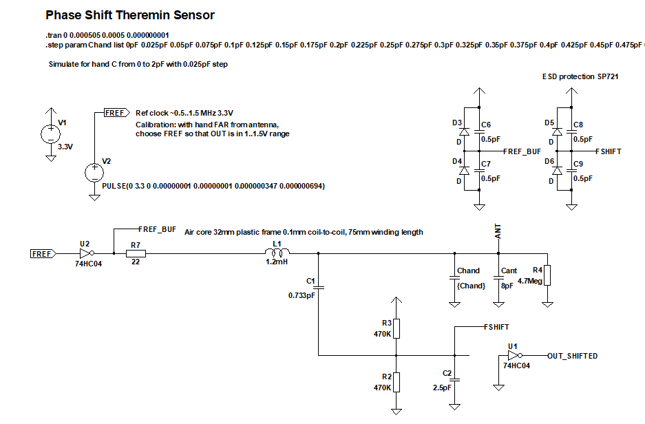
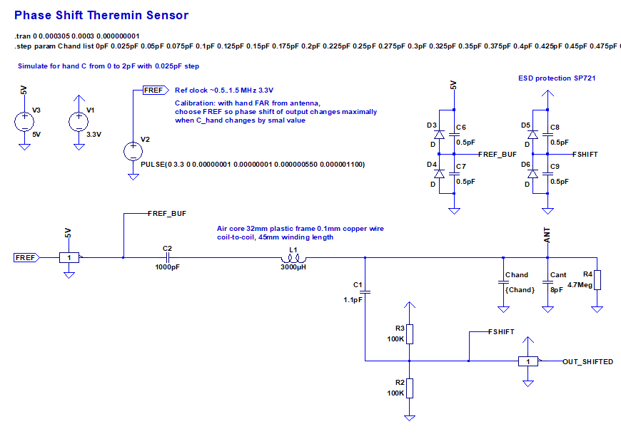
Let's calculate theoretical sensitivity of new schematic - with 1pF ESD protection device and 2.5pF buffer invertor.
4.7Meg resistor is connected between antenna and ground to simulate energy loss of real device.
Resistor betwen F_ref buffer and L input, R_q, is set to 22 Ohm. Direct connection (R_q=0) gives better sensitivity by ~20%. R_q=33 works, too. R_q=68 limits output current by allowed 50mA if shorted to 0 or 3.3V, but visible reduces Q.
Centering resistors set to 470K. Tried 100K and 1Meg - no visible difference.
C for feeding output buffer is set to 2.2pF/3
Resistor between cap and centering resistor breaks resonance, so I removed it.
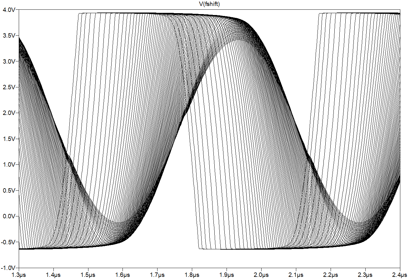
Simulation (C_hand step is 0.025pF):
LTSpice model (github link):
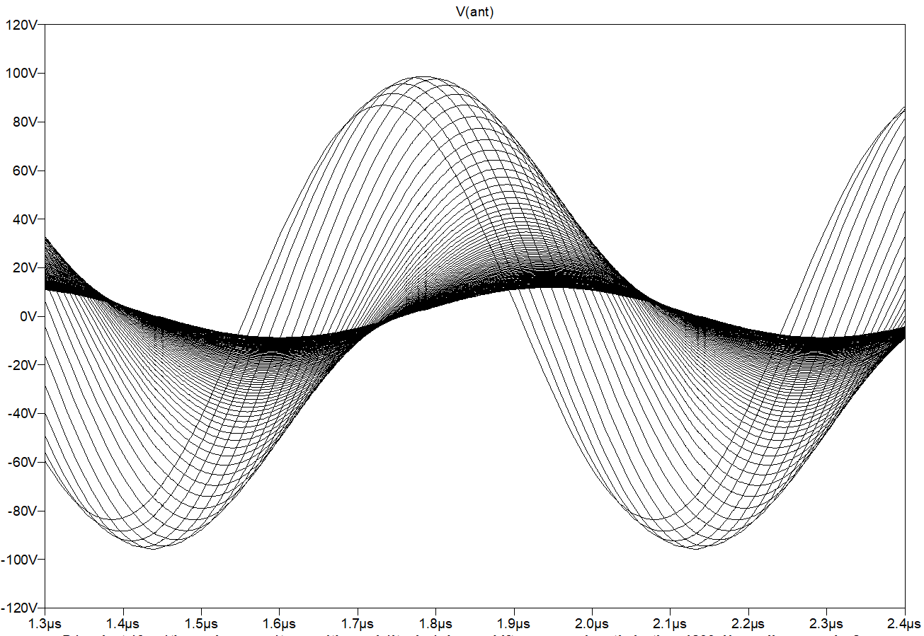
Antenna voltage swing is +-100V:
Output buffer invertor is disconnected and replaced with 2.5pF cap to simulate input capacitance of invertor planned to use
Now let's try to estimate sensor sensitivity.
Assuming C_hand is 1.5pF when hand is at 1cm from antenna, and reduced by 3.5 times each 10cm.
Per 1cm, it's 2^(log2(3.5)/10)=1.133461582
It corresponds to log2(1.133461582)=0.18 bits loss per 1cm of hand distance.
Table of C_hand for hand distances with 1cm step:
Code:
 dist, cm  C_hand, pF      Bits lost
 --------  ----------      ---------
 1         1.50000000      0
 2         1.32337966      0.18
 3         1.16755581      0.36
 4         1.03007974      0.54
 5         0.90879105      0.72
 6         0.80178373      0.9
 7         0.70737618      1.08
 8         0.62408483      1.26
 9         0.55060078      1.44
10         0.48576925      1.62
11         0.42857143      1.8
12         0.37810847      1.98
13         0.33358737      2.16
14         0.29430850      2.34
15         0.25965459      2.52
16         0.22908106      2.7
17         0.20210748      2.88
18         0.17830995      3.06
19         0.15731451      3.24
20         0.13879121      3.42
21         0.12244898      3.6
22         0.10803099      3.78
23         0.09531068      3.96
24         0.08408814      4.14
25         0.07418702      4.32
26         0.06545173      4.5
27         0.05774499      4.68
28         0.05094570      4.86
29         0.04494700      5.04
30         0.03965463      5.22
31         0.03498542      5.4
32         0.03086600      5.58
33         0.02723162      5.76
34         0.02402518      5.94
35         0.02119629      6.12
36         0.01870050      6.3
37         0.01649857      6.48
38         0.01455591      6.66
39         0.01284200      6.84
40         0.01132990      7.02
41         0.00999584      7.2
42         0.00881886      7.38
43         0.00778046      7.56
44         0.00686434      7.74
45         0.00605608      7.92
46         0.00534300      8.1
47         0.00471388      8.28
48         0.00415883      8.46
49         0.00366914      8.64
50         0.00323711      8.82
51         0.00285595      9
52         0.00251967      9.18
53         0.00222299      9.36
54         0.00196124      9.54
55         0.00173031      9.72
56         0.00152657      9.9
57         0.00134682      10.08
58         0.00118824      10.26
59         0.00104833      10.44
60         0.00092489      10.62
61         0.00081599      10.8
62         0.00071991      10.98
63         0.00063514      11.16
64         0.00056035      11.34
65         0.00049437      11.52
66         0.00043616      11.7
67         0.00038481      11.88
68         0.00033950      12.06
69         0.00029952      12.24
70         0.00026425      12.42
71         0.00023314      12.6
72         0.00020569      12.78
73         0.00018147      12.96
74         0.00016010      13.14
75         0.00014125      13.32
76         0.00012462      13.5
77         0.00010994      13.68
78         0.00009700      13.86
79         0.00008558      14.04
80         0.00007550      14.22
81         0.00006661      14.4
82         0.00005877      14.58
83         0.00005185      14.76
84         0.00004574      14.94
85         0.00004036      15.12
86         0.00003561      15.3
87         0.00003141      15.48
88         0.00002771      15.66
89         0.00002445      15.84
90         0.00002157      16.02
91         0.00001903      16.2
92         0.00001679      16.38
93         0.00001481      16.56
94         0.00001307      16.74
95         0.00001153      16.92
96         0.00001017      17.1
97         0.00000898      17.28
98         0.00000792      17.46
99         0.00000699      17.64
100        0.00000616      17.82
Simulation for 1.2mH inductor (air core 32mm frame diameter 0.2mm copper wire 75mm winding length)
with Series Resistance=32.909, Parallel resistance=2.680319Meg, Parallel capacitance=1.343pF
F_ref=1.436MHz, Q=330 according to Coil64
Stepping C_hand from 0pF to 2pF with 0.025pF step.
For Teensy 4.0 MCU working at 600MHz, FlexPWM resolution = F_BUS = F_CPU/4 = 150MHz
Divider for 150MHz to get value close to 1.436MHz is 110. So, period length in bits is log2(110)=6.78, for both edges measured one more big is added: 7.78
For F_CPU overclocked to 800MH, F_BUS=200MHz, and divider = 147. Period length in bits = 7.2, for both edges it's 8.2
Running simulation, and choosing widest 0.025pF step and calculating "zoom factor" - T_step / T_fref
0.0151/0.693 = 0.021789 = 2.18% of measurable range corresponds 0.025pF C_hand change near resonance.
MCU should tune F_ref with infinite hand distance to match peak of resonance (step of ref freq should cause max step in measured phase shift).
According to distance-to-C_Hand table, 0.025pF corresponds to hand distance ~33cm (C_hand is changed 1.5..0.025 for distances 1cm..33cm).
All bigger distances fall into single 0.025pF interval.
F_BUS=150MHz, log2(110*0.0218)+1=1.26+1=2.26 bits for non-overclocked MCU left for distances >33cm
F_BUS=200MHz, log2(147*0.0218)+1=1.68+1=2.68 bits for 800MHz overclocked MCU left for distances >33cm
(+1 bit is a bonus for both edges measurement)
To increase number of available bits we have to use averaging.
Default parameters of Teensy audio library: F_sample=44100, AUDIO_BLOCK_SAMPLES=128 give 44100/128=344.53 frames per second, frame length=(1/344.53)*1000ms=2.9ms
We have new measure results once per 1.436MHz cycle, 1436000 times per second, 1436000/344.53=4168 measures per 2.9ms audio frame.
If we do averaging for single audio frame w/o overlaps, we should get additional log2(4168)=12 bits for measured phase shift due to averaging.
Measured phase shift will be a number in range 0..110-1
Both edges give 0..110*2-1 = 0..220-1
Averaging (simple sum) of 4168 measurements gives values in range 0..220*4168-0..916960
Near resonance, for 0.025pF range, values will vary by 916960*0.0218=19989.728 log2 = 14.29
2.26+12=14.26 bits for non-overclocked Teensy 4 with F_BUS=150MHz
2.68+12=14.68 bits for overclocked Teensy 4 with F_BUS=200MHz
Let's check how number of available bits reduces after 33cm
Quantization - number of different values from sensor per cm of distance can be calculated as difference between output values with 1cm distance difference: log2(bits_left(dist))-log2(bits_left(dist+1cm))
Values per cm - expected number of different values from sensor averaged for 1 frame length, for distance changed by +-0.5cm
Code:
dist, cm  C_hand, pF  Bits lost  Lost after 33cm bits left  values per cm
--------  ----------  ---------  ---------------  ---------  -------------
33        0.02723162  5.76      0.00            14.26     2301.31
34        0.02402518  5.94      0.18            14.08     2031.37
35        0.02119629  6.12      0.36            13.90     1793.10
36        0.01870050  6.30      0.54            13.72     1582.77
37        0.01649857  6.48      0.72            13.54     1397.12
38        0.01455591  6.66      0.90            13.36     1233.24
39        0.01284200  6.84      1.08            13.18     1088.58
40        0.01132990  7.02      1.26            13.00     960.90
41        0.00999584  7.20      1.44            12.82     848.19
42        0.00881886  7.38      1.62            12.64     748.70
43        0.00778046  7.56      1.80            12.46     660.88
44        0.00686434  7.74      1.98            12.28     583.36
45        0.00605608  7.92      2.16            12.10     514.93
46        0.00534300  8.10      2.34            11.92     454.53
47        0.00471388  8.28      2.52            11.74     401.22
48        0.00415883  8.46      2.70            11.56     354.16
49        0.00366914  8.64      2.88            11.38     312.61
50        0.00323711  8.82      3.06            11.20     275.95
51        0.00285595  9.00      3.24            11.02     243.58
52        0.00251967  9.18      3.42            10.84     215.01
53        0.00222299  9.36      3.60            10.66     189.79
54        0.00196124  9.54      3.78            10.48     167.53
55        0.00173031  9.72      3.96            10.30     147.88
56        0.00152657  9.90      4.14            10.12     130.53
57        0.00134682  10.08      4.32              9.94        115.22
58        0.00118824  10.26      4.50              9.76        101.70
59        0.00104833  10.44      4.68              9.58        89.77
60        0.00092489  10.62      4.86              9.40        79.24
61        0.00081599  10.80      5.04              9.22        69.95
62        0.00071991  10.98      5.22              9.04        61.74
63        0.00063514  11.16      5.40              8.86        54.50
64        0.00056035  11.34      5.58              8.68        48.11
65        0.00049437  11.52      5.76              8.50        42.47
66        0.00043616  11.70      5.94              8.32        37.48
67        0.00038481  11.88      6.12              8.14        33.09
68        0.00033950  12.06      6.30              7.96        29.21
69        0.00029952  12.24      6.48              7.78        25.78
70        0.00026425  12.42      6.66              7.60        22.76
71        0.00023314  12.60      6.84              7.42        20.09
72        0.00020569  12.78      7.02              7.24        17.73
73        0.00018147  12.96      7.20              7.06        15.65
74        0.00016010  13.14      7.38              6.88        13.82
75        0.00014125  13.32      7.56              6.70        12.20
76        0.00012462  13.50      7.74              6.52        10.76
77        0.00010994  13.68      7.92              6.34          9.50
78        0.00009700  13.86      8.10              6.16          8.39
79        0.00008558  14.04      8.28              5.98          7.40
80        0.00007550  14.22      8.46              5.80          6.54
81        0.00006661  14.40      8.64              5.62          5.77
82        0.00005877  14.58      8.82              5.44          5.09
83        0.00005185  14.76      9.00              5.26          4.49
84        0.00004574  14.94      9.18              5.08          3.97
85        0.00004036  15.12      9.36              4.90          3.50
86        0.00003561  15.30      9.54              4.72          3.09
87        0.00003141  15.48      9.72              4.54          2.73
88        0.00002771  15.66      9.90              4.36          2.41
89        0.00002445  15.84    10.08              4.18          2.13
90        0.00002157  16.02    10.26              4.00          1.88
91        0.00001903  16.20    10.44              3.82          1.66
92        0.00001679  16.38    10.62              3.64          1.46
93        0.00001481  16.56    10.80              3.46          1.29
94        0.00001307  16.74    10.98              3.28          1.14
95        0.00001153  16.92    11.16              3.10          1.01
96        0.00001017  17.10    11.34              2.92          0.89
97        0.00000898  17.28    11.52              2.74          0.78
98        0.00000792  17.46    11.70              2.56          0.69
99        0.00000699  17.64    11.88              2.38          0.61
For 5 octaves set for note range, 1cm per halfnote, 1..61cm range we have 1cm per halfnote.
To see max working range, let's look when number of values per cm falls below acceptable.
At 57.5..58.5 cm range we see 101 distinct values. It's pretty good - one cent resolution.
At 75 cm distance, there are 12 distinct values. It's conditionally acceptable.
At 80 cm we see 6 values per halftone - should be audible if we are not considering automatic smoothing due to different measured values in different frames.
At 90 cm we fall below 2 values per halftone - can consider this as sensitivity limit.
So, I'm expecting 70-80 cm of practical playable distance from sensor with these parameters.
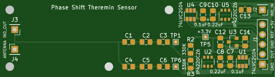
Sensor prototype PCB is updated:
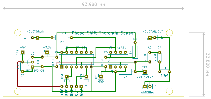
SMD version of sensor PCB is smaller - 50x20mm
It most likely will be placed inside 32mm inductor pipe (like I saw in D-Lev build thread).
(Big 1206 SMD components are used for easy soldering)
UPD: found that it's impossible to have similar high Q (zoomed in C_hand range) with 0.1mm coils like with 0.2mm one.
4mH 0.1mm gives x2 lower resonance, even w/o dumping R_Q.
Looks like 0.2mm coil must be used in this design, at least for Pitch sensor.
Posted: 11/28/2019 7:40:44 PM
Some findings from my phase shift sensor LTSpice models investigations.
Goal: find best configuration with good sensitivity (dT/dC), with frequency low enough to tune with reference frequency which is a divider of 150 or 200MHz (the lower frequency is, the lower is quantization of F_BUS/k-F_BUS/(k+1)).
Tried parallel LC tank fed via C - w/o success. Returned back to serial LC fed via R=0..68
Findings:
1) Increasing of Vcc from 3.3V to 5V increases sensitivity.
2) Buffer invertors can be connected in parallel - increases sensitivity.
3) It's ok to add capacitor between antenna and GND - reducing LC frequency, but almost w/o decrease of dT/dC.
As dT/dC I'm using values like (T_shift(C+0.1pF)-T_shift(C))*F_REF -- percent of working range covered by small capacitance change (0.1pF or 0.025pF) near resonance.
I've added 10pF between antenna and ground. Expected that sensitivity will be reduced twice because 0.1pF / C_ant decreases twice with increasing of C_ant. 0.1pF/8pF vs 0.1pF/(10+8pF)
It's a miracle, but sensitivity almost does not decrease with added C. It looks like Q increases with bigger C (in serial LC it's ~1/sqrt(C)) which compensates less dC/C relation.
Sensitivity decreases with C*K with K, but non-linearly. It rather looks like sqrt(k).
It allows to choose good L with high Q (although with high frequency w/o additional caps parallel to antenna), then add C parallel to antenna to decrease LC resonance freqency.
Lower frequency - lower quantization of available F_ref values, lower measurements rate (DMA transfers), less calculations when averaging sampled data in audio frame.
It makes no sense anymore to choose logic buffer IC and ESD protection diodes with low C_in.
Posted: 12/3/2019 6:31:32 AM
Testing on real HW should show if this approach is working, and if Teensy 4.0 MCU PWM module is precise enough to measure phase shift enough for use in theremin.
I've soldered simple prototype PCB:
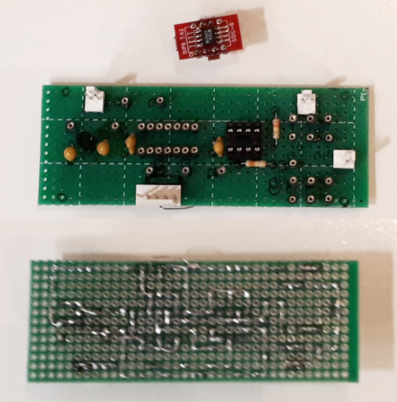
For 74HC04 and SP721 where are sockets for easy replacement. (E.g., experiment - what is better, 74AC04 or 74HC04).
Passive components to play with will be mounted to sockets, too: R for driving of inductor, C between antenna and input buffer, C between antenna and ground.
Posted: 12/9/2019 11:08:57 AM
Played a bit more with LTSpice simulation.
Found 74AHC1G04 spice model - to be used instead of 74HC04.
With 1..1.5mH inductor (0.2mm wire), F_ref is in range 1.3..1.5MHz for which quantization of possible values (integer division of F_CLK) is not enough for fine tuning to position near resonance.
With 0.1mm wire and 2-3mH inductor, with 0.6..1MHz F_ref, step of F_ref is fine enough to tune F_ref to have phase shift delta close to max possible value for far hand distance.
0.1mm inductor has bigger series R, and there is no such big Q gain if two buffers are connected in parallel (inductor drive current is smaller).
5V VCC instead of 3.3V on inductor drive buffer gives visible sensitivity improvement.
So, let's use separate buffer+ESD for driving of LC with 5V supply, and buffer+ESD for phase shifted input with 3.3V supply.
Small packages will be used for buffer and ESD protection.
Buffer: 74LVC2G04
ESD protection: IP4220CZ6
In LTSpice simulation, 74AHC1G04 is used.
Simulation results (C_hand varies from 0 to 2pF with 0.025pF step, left, widest 0.025 step corresponds to all hand distances > 33cm).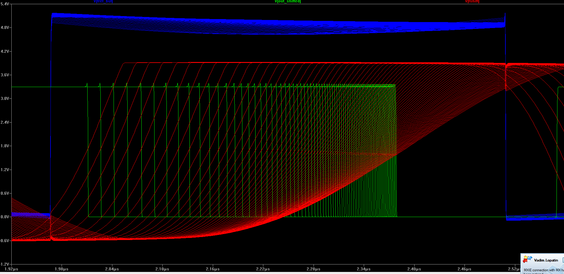
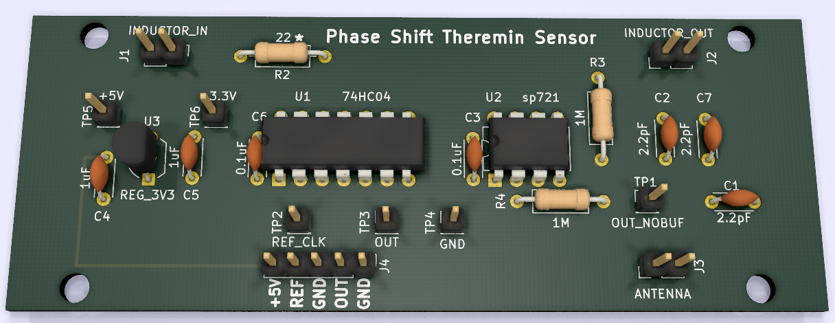
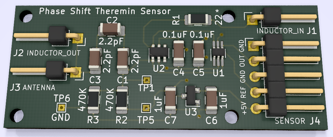
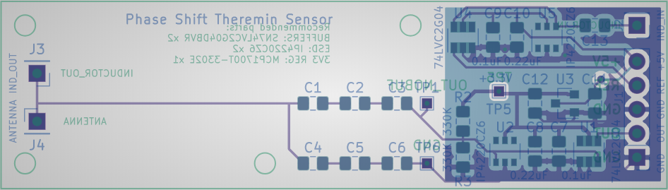
KiCad schematics and PCB 3D render.
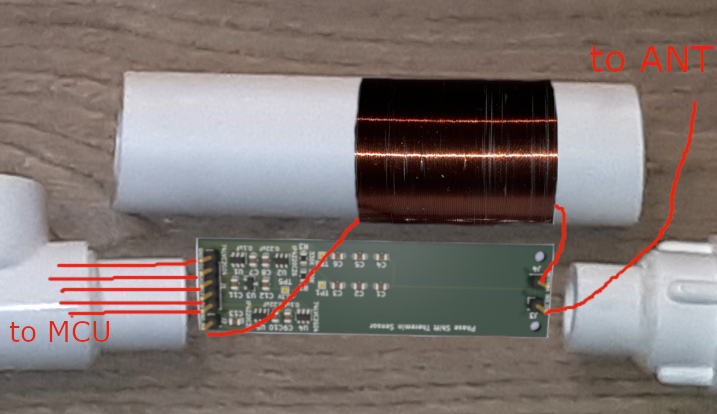
20mm width PCB will be placed inside 32mm plastic water pipe which serves as both antenna mount and inductor frame.
Almost unused 40-50mm of PCB is place where coils will be winded. So, main part of sensor PCB will be outside of inductor.
Bottom layer of PCB is GND plane for part outside of inductor.
Inductor side close near wide connector is input - there is 5V voltage swing.
Opposite side - inductor_out and antenna pins - has 80-150V of voltage swing.
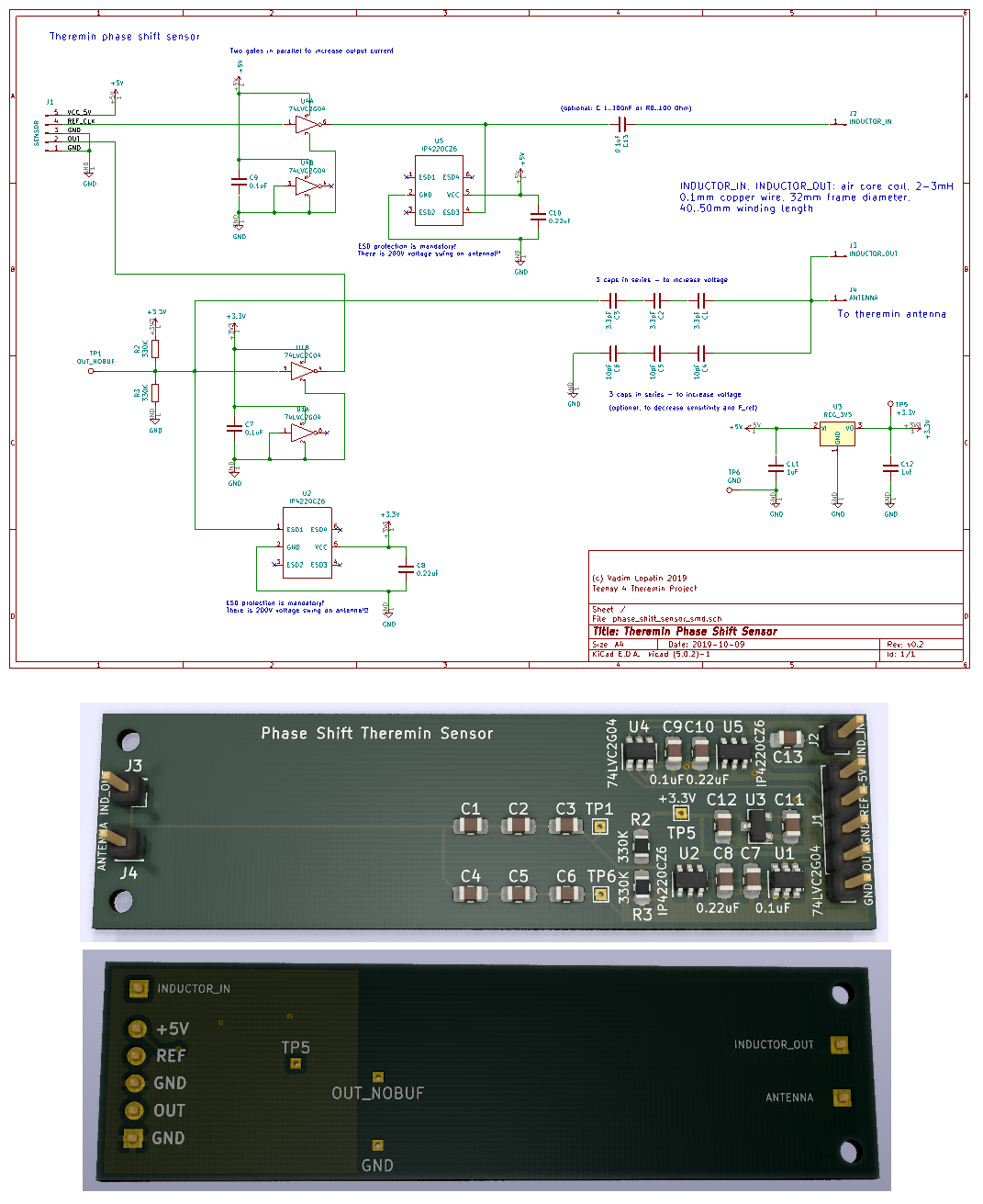
I'm planning just soldering of wires for inductor, antenna and main sensor connector.
Posted: 12/10/2019 7:24:00 AM
Pipe Monster v4 digital theremin antenna and sensors mounting.
Made of 20mm and 32mm PPL pipes and fittings.
Antenna sizes and distance between antennas - like in Etherwave.
32mm pipe pieces (coil + sensor PCB) will be fastened with screws to 20mm pipe pieces welded to fittings.
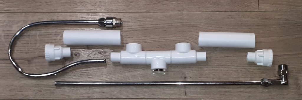
Bottom 1/2" female thread fitting - mic stand mount (1/2" water pipe male to 3/8" 24 thread female adapter needed) or table mount.
Two top 1/2" female fittings - for mounting of cabinet (with 1/2" to 3/8" male-female adapters as nuts). Cables from sensors will go through these 3/8" holes.
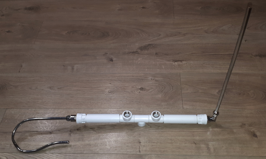
Inside 32mm pipe, there is
Coils should be winded with 0.1mm copper wire (40..50mm winding length) closer to antenna.
Sensor PCB should be oriented to have main parts outside of coils.

You must be logged in to post a reply. Please log in or register for a new account.