


NEW DESIGN
(once again)
I've changed plan once again - completely different theremin sensor schematic.
Phase shift sensor seems worse than classic heterodyne.
Teensy 4 will work overclocked (with heatsink) at 960MHz. This gives 240MHz bus clock - better timer resolutions.
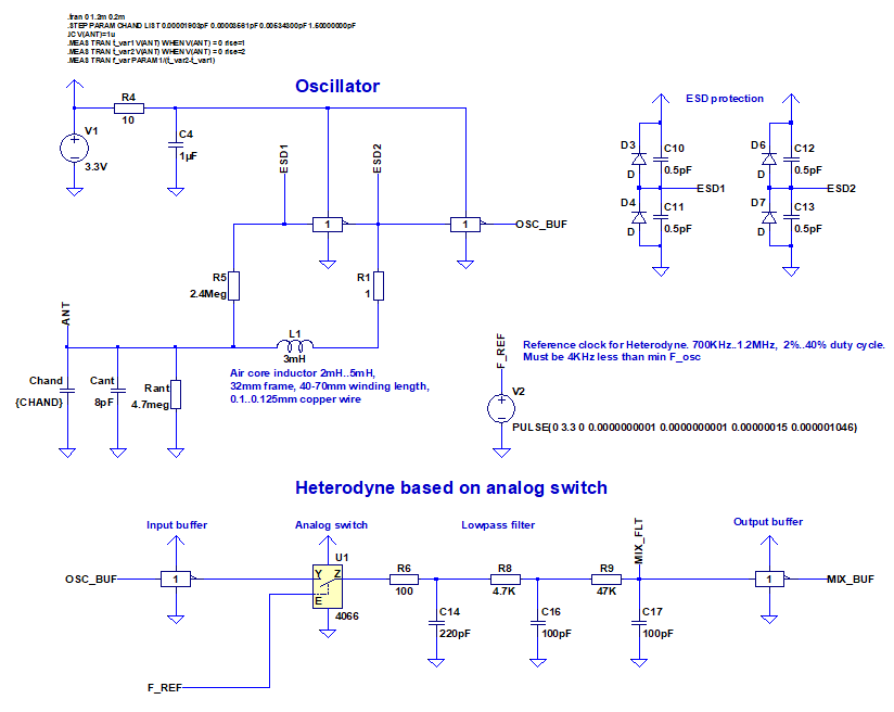
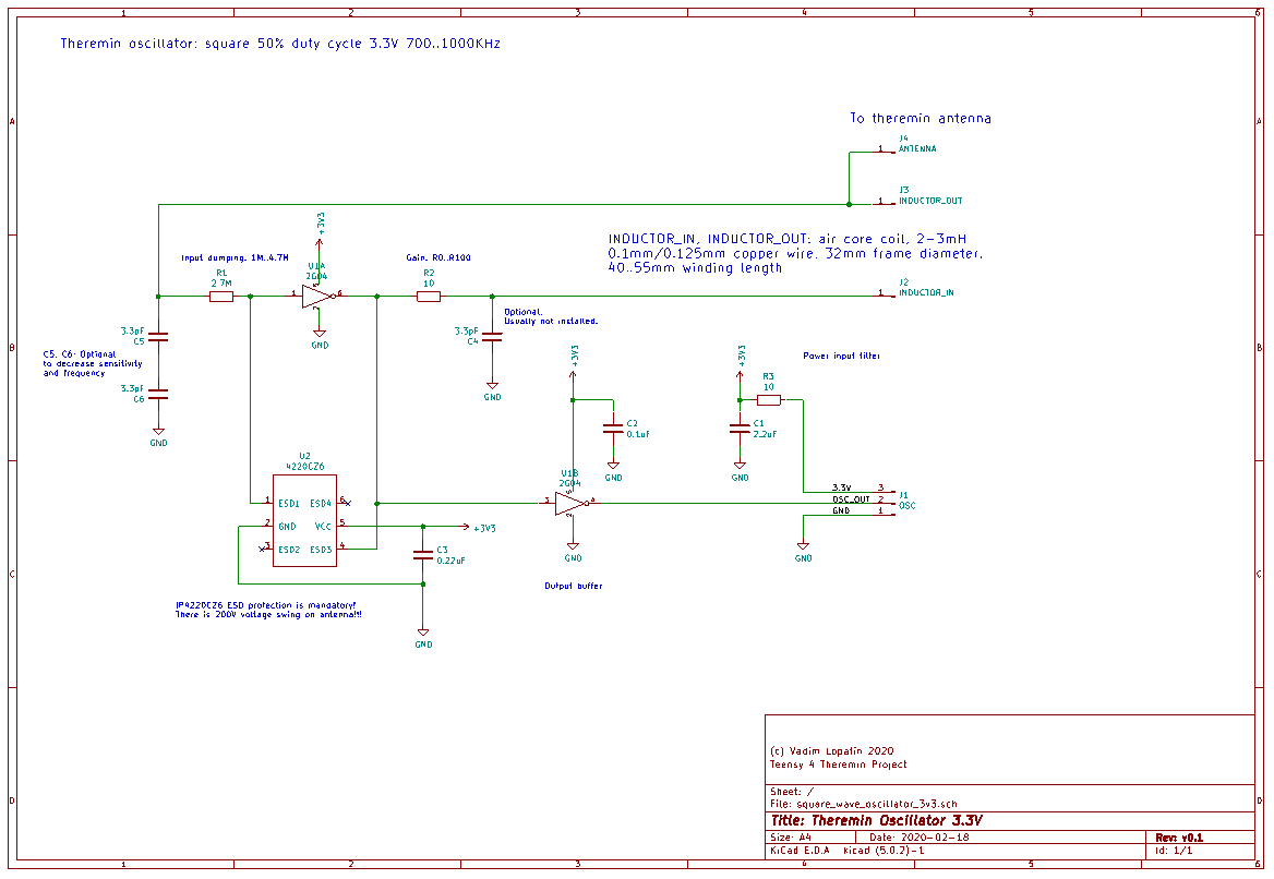
Instead of phase shift, let's use invertor based oscillator producing square wave ~800-1100KHz depending on inductor.
Heterodyne is based on analog switch IC : reference frequency signal with duty cycle < 50% is used to control switch.
Part of oscillator period is "sampled" every reference clock cycle, then averaged by LP filter, and converted to square.
This design should provide precise output, w/o aliasing unlike D-trigger mixers.
(Btw, does XOR+LP mixer have aliasing?)
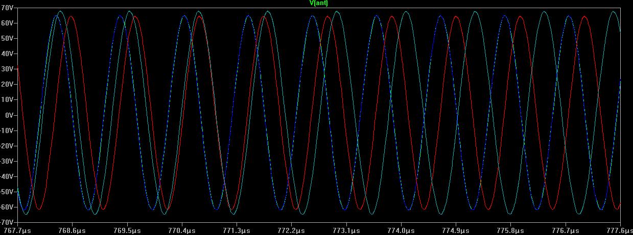
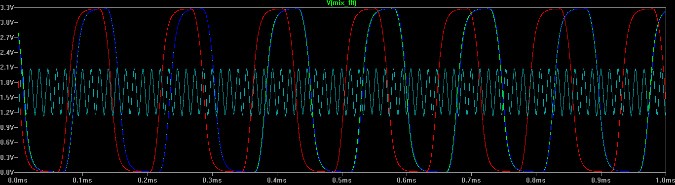
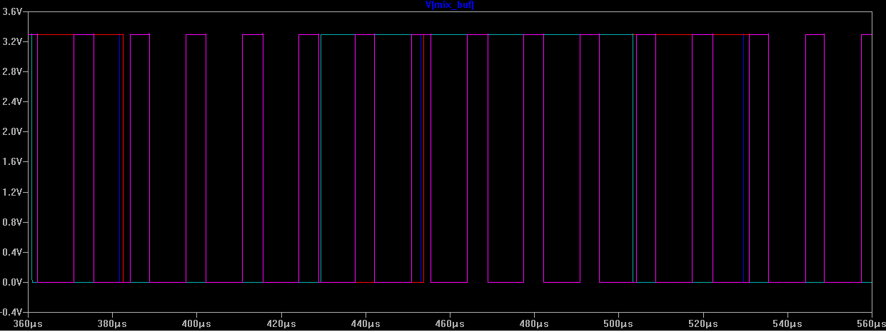
LTSpice model:
Antenna voltage:
Heterodyne filter ouput:
After heterodyne output buffer:
Oscillator produces F_max-F_min ~ 65KHz output frequency range (for far / near hand distances - C_hand=0..1.5pF).
Reference clock should be 4KHz bigger than minimal oscillator frequency (hand far from antenna) to avoid 16bit timer counter overflow.
240MHz cpu gives possible reference frequency values with steps ~3.5-4KHz.
So, heterodyne output will be in range 4KHz..70KHz .. 8KHz..74KHz depending on nearest available reference frequency.
Theoretical sensitivity - calculated assuming hand near antenna adds 1.5pF, and decreases 3.8 times each 10cm.
Bwelow, T_fbus is number of MCU F_BUS cycles (240MHz) in one output signal period.
Sensitivity near 80cm distance:
For 80cm C_hand = 0.00007550pF F_out = 4003.532 T_fbus = 59947.06598
For 81cm C_hand = 0.00006661pF F_out = 4003.084 T_fbus = 59953.77732
Difference in measured T_fbus for 80..81cm range is 6.711339738 F_BUS clock cycles (at ~4KHz)
Measuring of both raising and falling edges gives x2 better sensitivity: 13.42267948
Summary for 1ms (x4 times) gives 53.6907179 f_bus cycles.
So, at 80cm, we have ~53 distinct values measured for 1ms interval (0.2mm precision).
Bigger averaging gives bigger precision.
Sensitivity near 90cm distance:
For 80cm C_hand = 0.00002157pF F_out = 4000.813 T_fbus = 59987.8021
For 81cm C_hand = 0.00001903pF F_out = 4000.685 T_fbus = 59989.7221
Difference in measured T_fbus for 90..91cm range is 1.919994632 F_BUS clock cycles (at ~4KHz)
Measuring of both raising and falling edges gives x2 better sensitivity: 3.839989264
Summary for 1ms (x4 times) gives 15.35995706 f_bus cycles.
So, at 90cm, we have ~15 distinct values measured for 1ms interval (0.7mm precision).
Bigger averaging gives bigger precision.
Actually, even if no values outside 1ms frame are summarized, "autosmoothing" will work due to dithering between note frequencies calculated for sequential frames.
Oscillator PCB - KiCad schematic:
Oscillator PCB - KiCad 3d render (PCB size is 70x20mm):
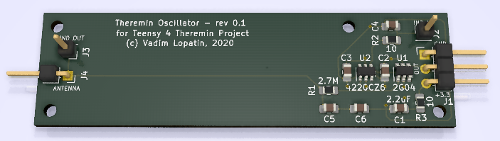
This PCB will be placed inside polypropylene water pipe - with coils winded on most of its length.
110mm length 32mm diameter pipe will be a part of antenna/cabinet mount (pipe monster design).
Coils will be either 50mm or shorter winding, or will overlap oscillator components on lower voltage side of inductor ("input" side).
Anyway it would be interesting how this oscillator would work inside coils.
Heterodyne PCB (dual channel) - KiCad schematic:
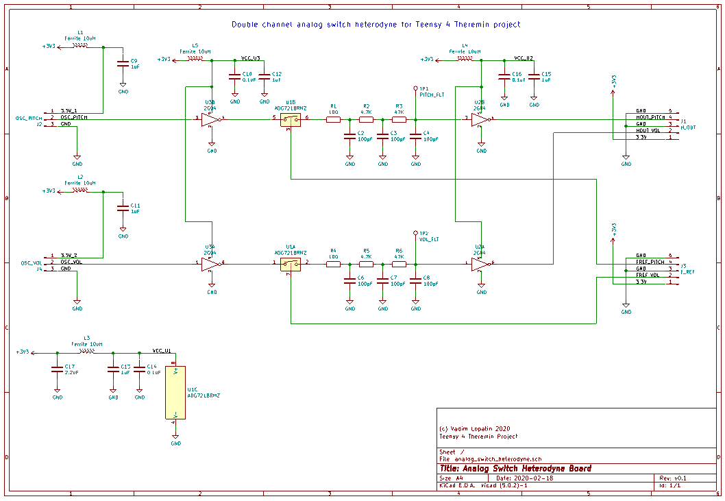
ADG721 is fast, and has low ON state resistance.
LVC2G04 is fast, and has low C_in
Performance should be much better than on simulation which uses slow 4066 switch IC.
Waveform on heterodyne LP filter output should look like closer to square with smooth raise and fall (sharpness depending on reference freq duty cycle).
For duty cycle near 50% it should be close to triangle. For shorter f_ref pulses, output will be closer to square.
Heterodyne PCB (dual channel) - 3d render (PCB size is 30x40mm):
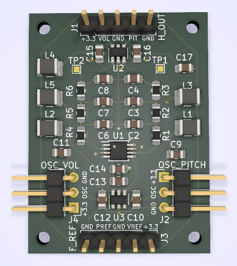
Each IC and each sensor (oscillator) connector has its own LC filter on power line.
Probably, it's overkill, and inductor may be replaced with small R or even shorten.
I just like symmetry of this dual channel PCB 
Going to order manufacturing on pcbway.com
KiCAD project and Gerber files in .zip archive can be found on GitHub: oscillator PCB, mixer PCB
