

This article is intended to chronicle my experience of construction and modifications of the Jaycar/Silicon Chip Theremin kit. It may resemble a blog-like structure, as I’ve been adding to it as I’ve been working on the unit. I hope it is useful to those wanting to try out this unit. This kit was purchased though Theremin Kits in Australia.
Introduction
I first came across the Jaycar/Silicon Chip Kit when a friend was bought one for Christmas. He’d successfully constructed it, and all it needed was some tuning! Hmmm, tuning I thought. Great! I suppose I’ll have to bring out the ‘scope, Frequency Counter, DVM, etc out of retirement for this one!
Then, I read the instructions. Phew! No need for a ‘scope. The ‘scope traces are just there for scare factor I think.
I’m unable to give you a heads-up on the kit contents, but suffice to say that nearly everything that was supposed to be there was in the packaging.
Unfortunately, the kit was supplied with two White, and two Black IF coils. I drafted up an email to Theremin Kits. Within a day, I received a reply asking for my postal address so that they can dispatch a replacement set of coils. Having done that, the coils arrived within a week from Australia! Fantastic service in my opinion. My friend had also written to Graeme, at Theremin Kits for help, and I know he was impressed with the level of support given. Graeme also replied to another email of mine where I’d asked for any tuning hints and tips. (The reply at the end of this article.) Thanks for all your help Graeme!
The resistors supplied are the 5-band variety, so may be a little difficult to read. Having said that, the instructions supplied contains a table to help those who may have some difficulty. Also, the component overlay shows only component values, and not their designations. Some components do have their designation shown. For someone troubleshooting, this could be a little frustrating when trying to locate a component by referring to the circuit diagram and tracing the PCB track.
Tuning
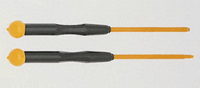
Well, tuning to the instructions was just something else! Plastic, ceramic or brass “trimmers” at the ready. Something similar to these:

Adjustment of voltages was easy enough, albeit a little on the sensitive side. There is an “erratum” in the instructions that states this very problem. The fix, it mentions is to solder a 100K resistor across the 1M resistor that’s across pins 1 and 2 of IC2b. This done and it’s just a tad better. I’ll just stick with it and hope for the best.
After a couple of days of working out the effect of adjusting the coils, I was on a mission to get this darned thing working. During this time I was recovering from pneumonia and all those antibiotics were certainly doing their job and messing with my mind! Tip, drugs and thinking certainly don’t mix!
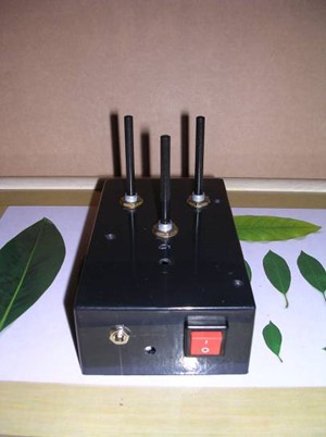
One thing I noticed was the box is a little on the small side when adjusting the coils. With the aerials fixed to the box, it’s difficult not to get close to them while tweaking! Ho hum, a little cosy, but workable.
Anyway, after a couple of hours, the tweaking was done as best as I could get it.
The instructions refer to the Reference Oscillator coil (T1) not requiring any adjustment. My experience showed that you will have to adjust it at some time, be it only a little.
The instructions also mention adjusting the pitch control so that bringing your hand closer to the aerial should decrease the pitch. As far as I know, most if not all Theremins operate in the opposite manner. I have adjusted T1 and T2 to give a null point when the hand is away from the aerial.
I also found that adjusting T3, post all adjustments improves upon the sensitivity of the volume aerial. With VR2 and T3 and T4 adjusted as per Max's instructions, the volume aerial was only effective between 1-5cm. Pretty poor I thought. "De-tuning" T3 improved this to around 15cm. The Volume fine-tuning control was set to mid-point.
Right! I'm happy. Now to put it all together.
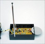
Ha!! Sucker!! It doesn't sound the same. Why? Well, as soon as anything comes close to the unit, it alters the circuit capacitance, but here, not only have you put a top on, but it contains a whopping big lump of metal. Not only metal, but a jolly good magnet!! Yup, the speaker is mounted on the top, hanging right over the board. OK, there's no getting away from that, so it's back to making slight adjustments to the Pitch, Reference and Volume oscillator coils. The lesson here is to make all your adjustments after applying all modifications, and securing the lid onto the case.
Theremin World and Max's article
Goody, all done and working! I'm ready to wrap it up and hand it back to my friend. Until that is, I stumble upon www.thereminworld.com after browsing MSN groups for a Theremin group (Theremin Players). The forum at Theremin Players seems to be a repository for spam now, but thankfully, the links section had a link to Theremin World.
Right, what do we have here? Straight to the schematics section for any ideas. There I am, browsing through all, well, almost all the schematics when after an hour or so, what is this I see? I notice Max's article on the Silicon Chip Theremin.
With the excitement of seeing this article, a Homer moment came over me! MMmmm.
Pseudo Moog
Then, a week or so later, Jason's uploaded his review of the EtherWave Pro. What a beautiful looking thing! Designed by an artist, not a techie, I see. Just look at the placement of the control dials, switches and LED!! Hmmm... I have an idea. (Now, visualise dreamy sequence ... Think bubble, wavy image)
OK dreaming over... Back to where I left off...
Max's article, cont...
I must have read through Max's article a hundred times before applying most of the mods. All I can say to anyone with this unit is, DO IT! The VR2 adjustment is still sensitive, but somewhat improved! I'd recommend using a multi-turn trimmer in place of the one supplied.
Pitch linearity is a noticeable problem with this kit, so I welcomed Max's modification of incorporating a ballast coil between the PCB and aerial.
Unfortunately I couldn't get the coil calculator to work, so maybe a quick pointer Max? Please?
I'd wound a short coil and soldered it to the PCB with a short wire to the Pitch aerial. It did seem to help somewhat with linearity, so I may stick with this or one with more turns later.
Most of Max's mods have been applied to the unit. The only mod I'd tried and removed was the two "L-shaped" wires used to modify the timbre. As Max mentions, the change in sound is a matter of personal taste.
Aerials
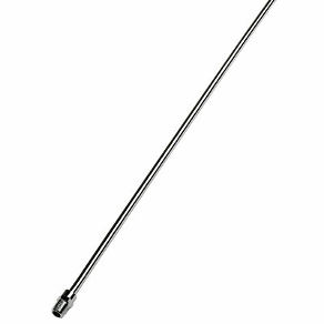
I'd thought of using an 8mm chrome-plated gas restrictor pipe available from all good DIY and plumbers stores for the aerials, or a chrome plated bathroom towel rail available from IKEA. You could also look at replacement Car aerials used to customise cars these days. Some interesting designs...
I popped in to B%26Q (may be Home Depot in the US), ready to buy a gas restrictor, and instead, left with a one-meter length of Aluminium tube, 6mm diameter with a 1mm wall. While looking at it in the store, this will do just nicely, I thought. And with that thought, comes another of how to bend the curve! The best way I could think of at the time is to make a wooden/MDF former with pegs, and then to bend the tube.
The Jig was made from a pine base and wooden dowel pegs. The circular form was the headstock of my lathe. Its diameter was perfect! You should be able to see the dimensions of the design from the picture. 20cm length, 5cm between the ends, and approx 9cm loop diameter. Bending the tube was very easy. Taken slowly, you shouldn't get any kinks at all. You should also be able to use this method with solid materials. As long as the pegs are secure, you shouldn't have any problems.
Take a look at the short video made from the stills at: http://www.thereminworld.com/files/LoopAerialConstruction.wmv
It's amazing how many methods of bending one can come up with when in a corner! By the way, the Gas restrictor costs just over $5, while the aluminium pipe was $1.50. Forever the bargain hunter!
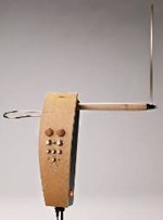
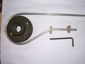
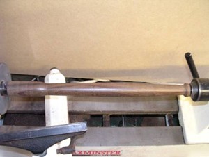
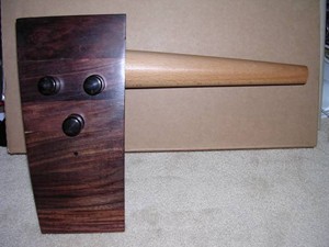
As I won't be using the Bee-sting car aerial for pitch control, a slight design change is in order. I've decided to maintain the conical feature as on the EtherWave Pro on the Rosewood boom.

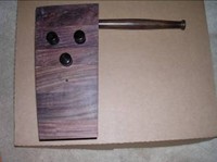
Having trouble getting hold of a long drill-bit to bore the centre hole in the rosewood boom, I have used the wooden (Beach, I think) stalk from a spare IKEA Kvintol lamp. Until I get hold of a long drill-bit, this will have to work for now, even if there is a slight colour mismatch!! I'm a little impatient like that!
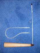
As for the Volume Aerial, I've thought that it would be a good idea to be able to adjust the angle of the loop at a fixed point. By adjusting the angle, it could be positioned for maximum comfort while playing. I may regret this later when it comes to playing after adjustment, as it may affect the tuning!! Hopefully, the Fine Tuning control will compensate for any variance.
Pseudo Moog, cont...
I have some Rosewood off-cuts in the garage, and a woodworking lathe I need to fire up after a long20break! OK, I may have to improvise with some power tools, but I think I could give it a go. Yup, you've guessed it! A custom Silicon Chip Theremin. I feel a new TV show coming on!! Something along the lines of MTV's "Pimp my Theremin".
I know Adrian will be surprised when he sees it!! It'll certainly be a little different from all the other Silicon Chip units out there! OK, it may not sound anything like an EtherWave Pro, or look like it for that matter, but it's different!
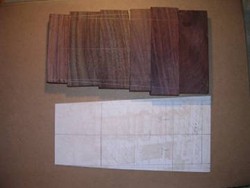
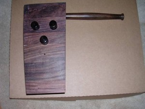
OK, you'll see from the pictures that I started off with planning the shape of the front panel. The EtherWave Pro's front panel looks like a laminate with a walnut-like veneer. Well, Rosewood is all I have, so will have to make do with it, and some nifty use of the power planer. Anyone wishing to donate a Tabletop Band Saw, Belt Sander, Table Saw, etc. please apply here!!
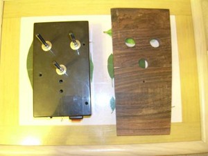
While the Rosewood pieces were drying, I got down to working out how it's all going to fit onto the back of the new panel. The only thing I could think of was to use the main part of the box as the front, with the lid being the back and housing the PCB. The lid had already been drilled to accommodate the speaker, power switch and volume control. As this would be hidden, I wasn't too concerned about the looks. To add to the existing holes, I'd be drilling more holes anyway for access to the coils, trimmer and Op-Amp.
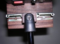
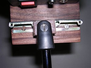
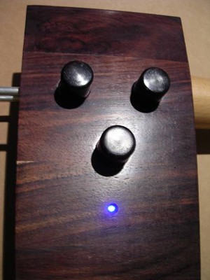
The front panel is now ready with all the appropriate holes to receive the potentiometers and LED (blue, of course!). It is best to drill any holes before sanding any curves, as it makes drilling easier and safer. At this point, I'm still working on turning the wooden aerial boom, and working out how to attach it to the case. You'll see from the pictures that I've retained the plastic nut glued to the case, and will be using the screw portion of the lamp holder. This is sawn off to around 6-8mm and glued onto the rosewood boom. This way, I don't have to use any ingenious screws and tube bolts!!
Now, there's something missing in the case. Yup, you've noticed it. Where is the speaker? Well, after a lot of thought, that will be mounted inside the case at the top. This my change to no speaker at all depending on its effect in that position so close to both aerials. The screened cable should help somewhat though.
After a phone call with Adrian, another modification is afoot! The internal speaker won't be used for most of the time, and will need to be switched off when plugged into an amp. No problem!! I wanted an excuse to get the same type switch used on the EtherWave Pro with the LED built-in to the toggle shaft!! Yippee!!!! Now the trick will be how to mount it without the retaining nut being visible! I have an idea! A vertical slot for the shaft, and then drill out the back of the faceplate to hold the switch with hot or epoxy glue. Done! Later I realised that all you need to do is to turn the volume control to its minimum position! Duh!!
I'm still trying to perfect my sign-writing skills, I'll wait until I've improved before attempting such a potentially hazardous task. For now, it'll remain without legends for the three control potentiometers. I'll either use white enamel paint and brush the lettering or a white enamel craft-pen.
Mounting
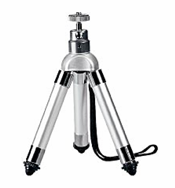
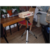
There is just about enough space to mount the finished unit to a mic/camera stand. Jessops in the UK used to sell a three-segment lightweight plastic camera tripod. Just remember that you may need to re-tune if mounted on the stand after tuning up.
My friend Andy, in the States has offered to send me a portable chrome camera tripod. I've accepted. Thanks Andy!
I've only a few days ago etched the Silicon Chip PCB for Andy, as he's quite keen to build one too. I think I'll be mounted in an RCA-type cabinet!! Pictures please!!

The tripod used is from Maplin Electronics. One of their portable microphone tripods. After a little head-scratching, I figured out a way to attach it to the panel. I've used a hard-disk mounting bracket screwed to the panel. The piece of the bracket now fixed to the panel is sandwiched between two thin pieces of wood off-cuts with a hole drilled into the centre. This hole now receives the captive nut, and a screw on the other side provides tension.
The effect of this arrangement is a clamping action which holds the bracket in place. Et voila!
The unit is a little heavier at the pitch aerial side, so I've adjusted the position of the "clamp" to maintain balance.
Well, I suppose I have to give it back now. It's become part of the family, but I knew I'd have to give it back one day! I know it'll be going to a good home. Visiting rights and maintenance have yet to be agreed upon. As I complete this Theremin, I'm also very close to complete recovery from the pneumonia, thank God!
Sounds
Summary
- Apply Max's modifications.
- Get a non-magnetic adjustment tool for the coils. (Plastic, Brass or Ceramic)
- Replace VR2 with a multi-turn trimmer.
- Replace the aerials. Especially the Volume aerial.
- Re-adjust T3 to improve the volume range.
- Consider using a different enclosure.
- Have a Homer moment.
Conclusion
All-in-all the Silicon Chip Theremin is a good unit to get you started in electronic construction and Theremins. The instructions supplied are fairly easy to follow for the novice. There is so much out there in terms of information and advice, you'd be foolish not to consider it.
The disc for controlling the volume is a tad small for any reasonable control. It will be best to replace this with something larger as described in Max's article and readjust VR2 and T4. The loop looks so much better!
The Pseudo Moog modifications are purely cosmetic. However, any physical changes will require retuning. It would be great to have a gallery of "cosmetically enhanced" Theremins at Thereminworld.com, don't you think?
The real changes are Max's modifications. All credit goes to him, as the unit is much more stable and has a wider range than the original. Thanks so much, Max!
The Switch with LED turned out to be far too large for this project, so disappointingly has been omitted. Also, I think I've messed up the rosewood boom, so until I can find a workaround, the beech Ikea lamp stalk will remain. The internal speaker has also been left out, for now.
Thanks to (in no particular order!):
- My friend Adrian, and his family for allowing me to take their Theremin away for so many months, and for giving me something to do while ill.
- My family for humouring me and cleaning up after the mess I'd made, and especially my wife for being so patient with me during hours of seclusion in the workshop!
- Graeme Gibson, from Theremin Kits for his support.
- Andy Tedds for his generosity and enthusiasm.
- Geoff Eggleston, for a great stock of Rosewood.
- Max Baars, for his expertise.
- Jason Barlie, at Theremin World for encouraging me to write this article.
Links
- http://www.thereminworld.com
- http://www.thereminworld.com/silicon_chip_theremin_modifications.html
- http://www.thereminkits.com
- http://www.siliconchip.com.au/cms/A_103277/article.html
- http://www.siliconchip.com.au/html/pcb00aug.htm
- http://www.maplin.co.uk
- http://www.radioshack.com/product.asp?cookie%255Ftest=1%26catalog%255Fname=CTLG%26product%255Fid=16-3650
Peace!
Appendix and Pictures
Graeme's Email
Graeme from Theremin Kit Sales sent me this email describing a tuning method without the need of a DVM:
Hi Abdul,
Here is the method for tuning the theremin by ear, without using a voltage meter. Many people do the tuning this way.
The T1 coil is the reference coil that the others are tuned against so its best not to move it much as any adjustment to this will put the others out requiring retuning. So if you set it to be more or less centred it will be fine.
The pitch is then adjusted by very fine adjustments to T2 to get a good pitch response from the telescopic antenna. Once you have a reasonable pitch response the final pitch fine tuning is done by raising and lowering the antenna. Just a few inches can make a surprising difference to the pitch response. Usually the antenna is set at 70-80%25 extension but you can experiment with this to see what you prefer.
T4 and VR2 are related to the volume circuit, some very fine movements with both T4 and VR2 are done to get good volume response from the horizontal plate.
The T3 is usually not adjusted, you should only need to change this if you find that the pitch and volume antennas interact. If this happens it is because the T1 and T3 are operating too close together so some fine adjustment to T3 would be needed. If T3 is adjusted however, the T4 and VR2 will need to be tuned again.
I hope this answers your question but please feel free to email again if you have any other queries.
regards
Graeme Gibson
Theremin Kit Sales
Pictures
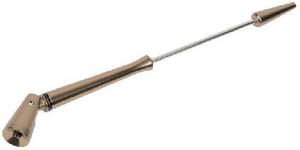
 Gas Restrictor 8mm 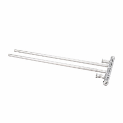 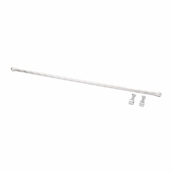 Baren Range IKEA |
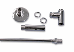 Gas Restrictor Kit 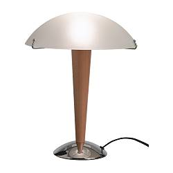 Kvintol Lamp (IKEA) |
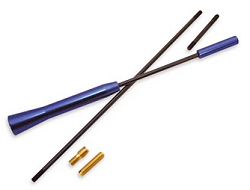  Bee-sting Car Aerials |
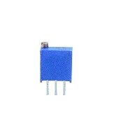 Multi-turn trimmer 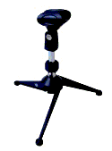 Maplin's Microphone Tripod |
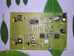
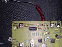
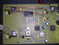
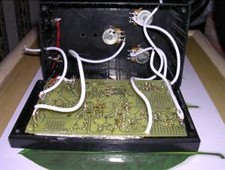
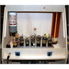
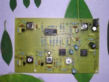 Fully built PCB with some of Max's mods applied 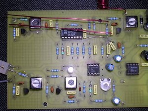 Showing how the two pieces of wire are attached to the pitch and ref oscillators. Notice the incorrect coil in the reference oscillator! |
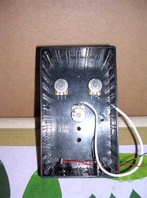 Mounting of Pots to the original case 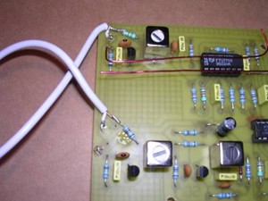 Screened wire attached for Pitch and Volume fine tuning. |
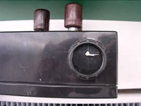
 Power input and switch repositioned to bottom of case. 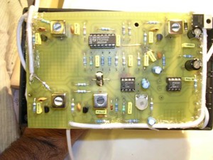 Screened cable for Aerials routed and hot-glued on PCB |
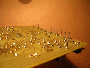 PCB Pins now on track side, PCB will be mounted lid.  PCB hot-glued to lid. |
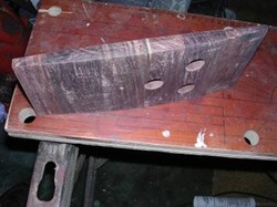
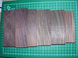 Rosewood blocks glued to form new panel. 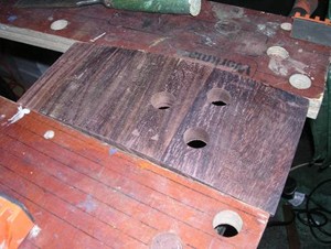 Front panel drilled, shaped and sanded. |
 Friends for life! (Now you see it) 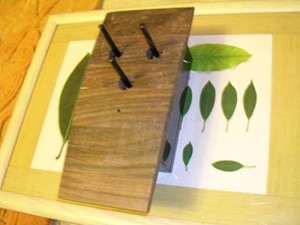 The happy coupling! (Now you don't) |
 Rosewood Pitch aerial boom. 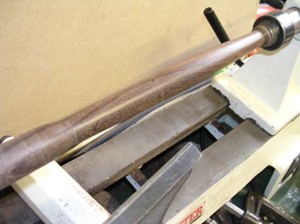 |
 Final Polish for knobs 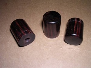 Three of a kind! |
 Just needs a smile now! 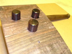 |
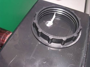 Alternative boom mount glued to case 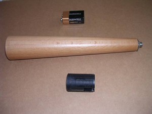 Alternative Boom from IKEA Kvintol Lamp |
 Beech Boom fitted 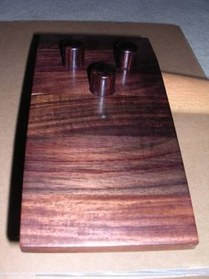 Faceplate polished |
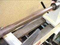
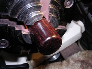
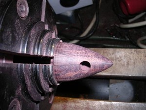 Boom cone on lathe 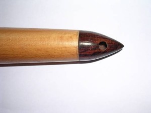 Finished |
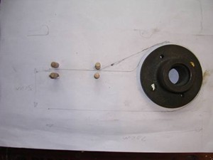 Volume Aerial Jig 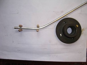 First bend |
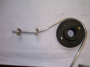 Round we go 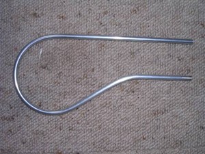 Finished |
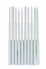
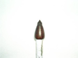 Pitch Aerial tip 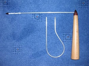 The set |
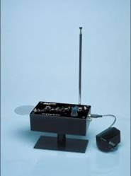
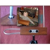
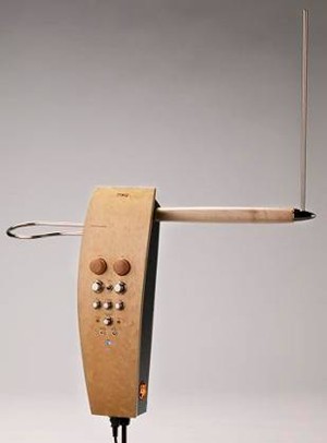 "Mock-up" before final adjustments 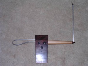
Nah, just kidding! |
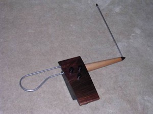 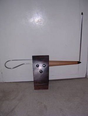
Another view |
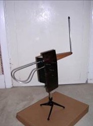
 Mounting bracket and tripod 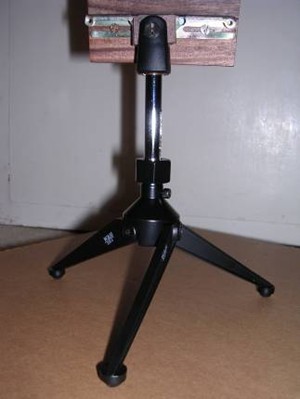 |
 We have Ignition! 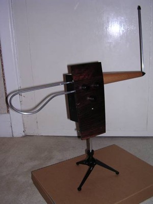 The Final Unit! |
%A9 Abdul K. Nathekar 2005 for www.thereminworld.com


