

Introduction
Acknowledgements – Arthur Harrison provided enough data on his website to inspire me to attempt constructing a replica RCA Theremin. I knew that I would never own one and I had actually never seen one except in pictures. Making one was as close as I could get.
History
The history of the invention of the Theremin by Leon Theremin is well known so I won’t go into it again except to say that his invention opened up a new world of electronic musical instruments from the Theremin to the Ondes Martenot to the modern synthesizers we see today. My inspiration probably started with the movie Forbidden Planet, which still has some great Theremin-like sounds. My first Theremin was a design by Moog published in Radio and Television News in 1954 which I built in the mid 1970’s. Parts for tube equipment were hard to find even then and I had to have two of the TV horizontal sweep coils required in the circuit wound by the original manufacturer. This Theremin ended up in a rock band.
Preparations
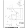
Gathering data – My first efforts went into gathering data. I searched the web for all the data, pictures, and general information I could find. The most useful was the RCA Service Manual and Arthur Harrison’s website. His website had specific information on some of the coils and capacitors that were not spelled out in the RCA Manual and a redrawn schematic that made deciphering the circuit much easier. Unfortunately there was no source for some of the components but I decided I would just have to figure them out.
Gathering parts – I have restored antique radios for about 10 years and have been a amateur radio operator since 1955 and being the type that never throws anything away, I have a large collection of vintage parts. I dug through what I had and found most of the power supply and a lot of the main chassis parts. The critical missing components were the chassis, audio transformers, some tubes, and the coil forms. I used a cardboard mailing tube for the main coils and the oscillator coils were wound on another cardboard tube. Fortunately most of the missing components were available from Mouser Electronics or Antique Electronic Supply. Dimensions of the chassis and any other parts were scaled from drawings or photographs that I found on the web.
The coils I could wind but the tubes and the audio transformers had to be found. All the original tubes are available but three, the two 171A’s and the 120, are getting scarce and very expensive. I decided to try a 31 in place of the 120 and I had two 71A’s, a more modern version of the globe-shaped 171A’s, along with the other tubes.
I knew that I couldn’t exactly duplicate the original instrument because many of the parts and values were unavailable and unknown and I had never seen a real instrument. My goal was to use what I could find that most closely duplicated the instrument both physically and electronically and maintain the overall feel of the original Theremin.
Power Supply
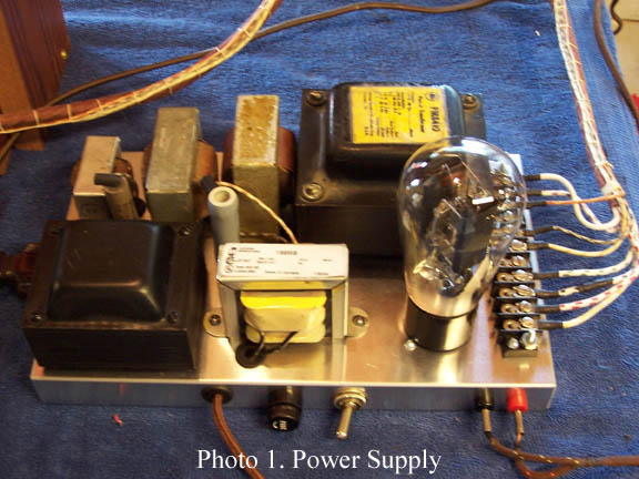
The power supply is typical of the time (1928) utilizing three chokes to do much of the filtering because high value capacitors were very large. The chassis I used was 10 in wide, 6 in deep and 1 in high. The size was scaled from photographs and the Service Manual. I tried to use the same layout as RCA used with adjustments for the physical size and shape of the parts I had. Nothing in the layout is critical. The power transformer voltage I had was too high so I had to use a large power divider resistor to get voltages suitable for the vintage tubes. (Photo 1)
Main Chassis
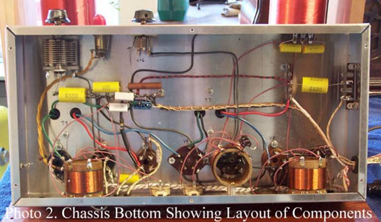
The chassis I used was 14 in wide, 8 in deep and 3 in high. The size was scaled from photographs and the Service Manual. Again, I tried to use the same layout as RCA used with adjustments for the physical size and shape of the parts I had. The oscillator coils are mounted at right angles to each other to limit any coupling between the coils. The chassis I used provided a lot of extra room because it turns out it is larger than the original and modern components are much smaller than the old parts. I used the same layout for all the components including the tubes, coils, transformers and all the capacitors and resistors. This left plenty of room for parts and kept the look of the original Theremin. (Photo 2)
Coils
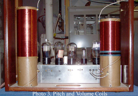
Pitch and Volume Coils – A five inch coil form was not to be found so I decided to use a 5 3/16 in mailing tube. I cut the tube to the original length and sealed it with varnish. I calculated the impedance of the original coils and then back-calculated the length of the windings based on the larger diameter. The critical dimensions in a solenoid-type coil are the diameter, length, and number of turns. The wire size was calculated based on close winding the necessary turns per inch which turned out to be #36. The original coils were wound with double cotton covered wire which is difficult to get now so I used enamel coated magnet wire. The necessary hardware for connecting and mounting the coils was fabricated and the coils wound by hand. (Photo 3)
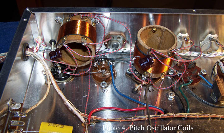
Pitch Oscillator Coils – The dimensions of the fixed and variable pitch oscillators were available so the only challenge was the construction. Varnished 1 3/4 in cardboard tubes were used as forms. (Photo 4)
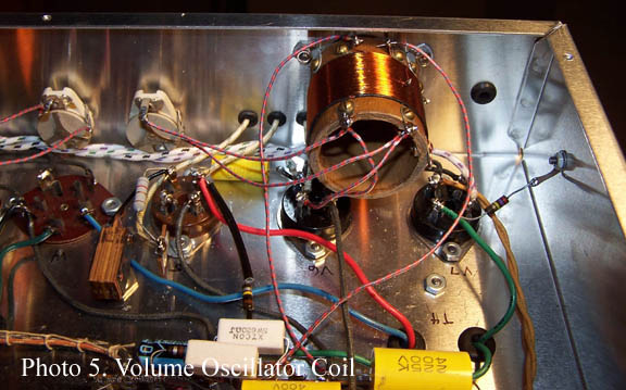
Volume Oscillator Coil – No information was available on the volume oscillator coil or associated capacitors except the diameter and that the capacitors looked physically the same. A cardboard coil form was used as in the pitch oscillators. I decided that RCA would probably use the same coil for both the pitch and volume oscillators because it would be cheaper. I assumed that they would vary the parallel capacitance to get an oscillation frequency different than the pitch oscillators. I made all the coils the same and expected to have to find the correct parallel capacitance experimentally. (Photo 5)
Concentrating coil – The concentrating coil is a relatively high inductance coil located inside the large pitch coil. Information was that the inductance needed was 20 mH and I had 15 and 5 mH chokes so I connected them in series.
Audio Transformers
The two audio transformer impedances were unknown so I used transformers made by Chicago Standard Transformer Corp. Model A-53 with a 1:3 ratio, still commercially available. My experience with these old tubes and circuits is that they aren’t too fussy about impedances.
Multi-Section Resistor
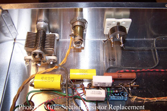
RCA used a multi-section, power-style resistor for several resistances required by the circuit. There is no apparent reason for this so I mounted a large terminal strip in the same location that RCA used and attached discrete resistors along the strip to approximate the original. (Photo 6) This also provided a convenient place to mount some other components.
Antennae
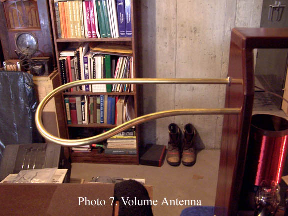
The antennae had to look like the original RCA Theremin. The information I had was that they were 7/16 in diameter, the length of the pitch antenna was 17 in, and some photographs. I scaled the volume antenna from the photographs and made a jig to bend rod around to get the right size and shape. I used brass rod to form the antennae. Rod is easier to work with because it does not collapse like tubing does when you bend it. The rod was heat treated so I had to anneal it before bending. (Photo 7)
Initial Operation
In order to test the pitch and volume sections separately and not expecting either section to work, I put two volts on the 31 tube (replacing the 120) so that the volume part of the circuit would have the volume all the way up. The RCA Theremin uses the 120 tube to vary the audio gain by varying the tube filament voltage (i.e. filament temperature) and therefore the amount of current flowing through the tube. Many early 1920’s radios used the same method to control the volume. As the resonant frequency of the large coil, which is varied by hand capacitance, approaches the resonant frequency of the volume oscillator, more current flows in the large coil and therefore in the secondary of the large coil which powers the 120 filaments.
Amazingly enough, after the smoke test was successful (no smoke), the pitch circuitry worked fine from the start and I had only to tune the unit as described in the RCA Service Manual. All the known values and dimensions seemed to work well.
I then removed the two volts from the 120 tube and all was quiet. I checked to see if the oscillator was working and it was but not near resonance with the large coil. I then started removing the capacitance that was in parallel with the oscillator coil to bring it closer to the large coil. As I approached the correct value the volume worked but was backwards (got louder as your hand got closer to the antenna) and I ultimately removed the 1000 pF capacitor across the oscillator coil leaving just a 100 pF trimmer to get on the correct side of resonance and proper operation.
Completion
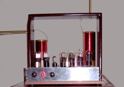
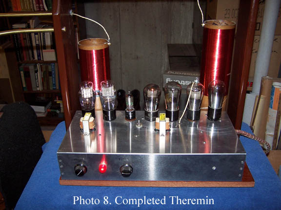
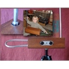
I made a base similar to the original RCA Theremin and a frame for the antennae locating them in the same position as the original. I decided that I liked the exposed chassis and coils so no cabinet was necessary. With the stained and varnished base and antenna frame, antennae, the large glowing tubes, and the large coils, the unit looks like a Theremin should. (Photo 8)
Conclusion
Subsequent to my constructing the replica RCA Theremin I had access to an original RCA Theremin thanks to the Audities Foundation. I measured all the component values and dimensions of the coils. The available information was correct for the pitch oscillator circuits but my assumptions for the volume oscillator circuit were wrong. The oscillator coil is different as is the parallel capacitance. Fortunately removing the parallel capacitance from the circuit resulted in an oscillation frequency that worked.
The audio transformers I used work fine. The waveform and tone of the replica is somewhat different than an original RCA Theremin, possibly due to these different transformers.
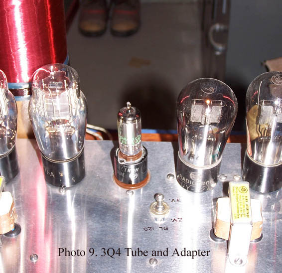
The 31 tube does work but the response time is a little slower than the 120. I made a socket adapter and used a 3Q4 miniature tube and it works about as well as the 120 and is easy and cheap to obtain. (Photo 9) The switch changes the filament voltage from 2 to 3 volts. A 01A tube can be substituted for the 171A audio amplifier and actually works better. A 171A is necessary in the volume oscillator because the 01A will not oscillate.
This was a major project that was a challenge from start to finish. All the component values are now known so anyone with perseverance and a little experience can make their own replica RCA Theremin. Remember that this instrument uses lethal voltages that many transistor-era constructors are not familiar with.
Notes
- Arthur Harrison’s website is at: home.att.net/~theremin1/index.htm
- Copyright © by Mark McKeown, 2005. It is ok to use this data but please give me credit.


